User's Guide
Page 44
...conversion Interfaces: Internal External Speaker Internal speaker amplifier Volume controls Stereo Digital Microphone Array Windows Vista® Windows XP two-channel high definition audio (Azalia) IDT STAC9205 Codec 24-bit (analog-to-digital and digital-toanalog) high definition audio ...(Azalia) microphone-in connector, stereo headphones/speakers connector one 4-ohm speaker 2-Watt channel into 4 ohms keyboard shortcuts, program menus supports Windows Vista native microphone processing includes Knowles Intellisonic microphone processing Display Both ...
...conversion Interfaces: Internal External Speaker Internal speaker amplifier Volume controls Stereo Digital Microphone Array Windows Vista® Windows XP two-channel high definition audio (Azalia) IDT STAC9205 Codec 24-bit (analog-to-digital and digital-toanalog) high definition audio ...(Azalia) microphone-in connector, stereo headphones/speakers connector one 4-ohm speaker 2-Watt channel into 4 ohms keyboard shortcuts, program menus supports Windows Vista native microphone processing includes Knowles Intellisonic microphone processing Display Both ...

User's Guide
Page 180
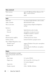
1 2 3 4 5 6 1 display 3 display connector pull-tab 5 antenna cables (3) 2 M2.5 x 5-mm screws (5) 4 display cable connector 6 antenna channel 6 Feed the Mini-Card antenna cables from the bottom through the cable channel to the top of the system. 7 Loosen the five M2.5 x 5-mm screws. 8 Turn the system upside-down and remove the base grip: a Remove the two M2.5 x 5-mm screws. 180 Adding and Replacing Parts
1 2 3 4 5 6 1 display 3 display connector pull-tab 5 antenna cables (3) 2 M2.5 x 5-mm screws (5) 4 display cable connector 6 antenna channel 6 Feed the Mini-Card antenna cables from the bottom through the cable channel to the top of the system. 7 Loosen the five M2.5 x 5-mm screws. 8 Turn the system upside-down and remove the base grip: a Remove the two M2.5 x 5-mm screws. 180 Adding and Replacing Parts
User's Guide
Page 182
... the palm rest, then the keyboard will not sit flat on the base. 2 Feed the Mini-Card antenna cables from the top through the antenna channel to the bottom of the palm rest. Align the shrink tube that was removed from the base, and place the display assembly to the edge...
... the palm rest, then the keyboard will not sit flat on the base. 2 Feed the Mini-Card antenna cables from the top through the antenna channel to the bottom of the palm rest. Align the shrink tube that was removed from the base, and place the display assembly to the edge...
User's Guide
Page 184
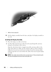
1 2 3 4 5 6 1 display 3 display connector pull-tab 5 antenna cables (3) 2 M2.5 x 5-mm screws (5) 4 display cable connector 6 antenna channel 4 Tighten the five M2.5 x 5-mm screws. 5 Close the Tablet-PC and turn it around so that you can access the back of the rotating hinge. 6 Tighten the two M2.5 x 5-mm screws on the top of the rotating hinge. 184 Adding and Replacing Parts
1 2 3 4 5 6 1 display 3 display connector pull-tab 5 antenna cables (3) 2 M2.5 x 5-mm screws (5) 4 display cable connector 6 antenna channel 4 Tighten the five M2.5 x 5-mm screws. 5 Close the Tablet-PC and turn it around so that you can access the back of the rotating hinge. 6 Tighten the two M2.5 x 5-mm screws on the top of the rotating hinge. 184 Adding and Replacing Parts

User's Guide
Page 194
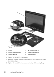
5 Remove any installed Mini-Cards (see "Removing a Mini-Card" on page 171). 6 Remove the palm rest (see "Removing the Palm Rest" on page 186). 7 Remove the system board (see "Removing the System Board" on page 189). 8 Remove the two M2 x 3-mm screws. 9 Remove the pen missing cable and whip antenna cable from their routing channels, then lift the pen assembly and whip antenna assembly from the base. 1 2 3 4 5 194 Adding and Replacing Parts
5 Remove any installed Mini-Cards (see "Removing a Mini-Card" on page 171). 6 Remove the palm rest (see "Removing the Palm Rest" on page 186). 7 Remove the system board (see "Removing the System Board" on page 189). 8 Remove the two M2 x 3-mm screws. 9 Remove the pen missing cable and whip antenna cable from their routing channels, then lift the pen assembly and whip antenna assembly from the base. 1 2 3 4 5 194 Adding and Replacing Parts

User's Guide
Page 195
... pen-missing cable whip antenna cable Installing the Pen and Whip Antenna Assembly 1 Seat the pen-missing cable and whip antenna cable into their routing channels.
... pen-missing cable whip antenna cable Installing the Pen and Whip Antenna Assembly 1 Seat the pen-missing cable and whip antenna cable into their routing channels.
User's Guide
Page 232
... is damaged or your computer has a virus, ensure that uses your unique fingerprint to authenticate your user identity to illuminate liquid crystal displays, such as 7.1 channels of up to many processor operations. C C - A type of bootable media.
... is damaged or your computer has a virus, ensure that uses your unique fingerprint to authenticate your user identity to illuminate liquid crystal displays, such as 7.1 channels of up to many processor operations. C C - A type of bootable media.
User's Guide
Page 234
... - A round, six-pin connector that allows certain types of hardware and software companies who develop management standards for spreading data over multiple disk drives. dual-core - direct memory access - dual display mode - A channel that conforms to a desktop workspace. DRAM - DVD recordable -
... - A round, six-pin connector that allows certain types of hardware and software companies who develop management standards for spreading data over multiple disk drives. dual-core - direct memory access - dual display mode - A channel that conforms to a desktop workspace. DRAM - DVD recordable -