Owners Manual
Page 3
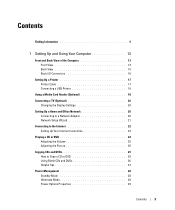
Contents Finding Information 9 1 Setting Up and Using Your Computer 13 Front and Back View of the Computer 13 Front View 13 Back View 15 Back I/O Connectors 16 Setting Up a Printer 17 Printer Cable 17 Connecting a USB Printer 18 Using a Media Card Reader (Optional 18 Connecting a TV (...
Contents Finding Information 9 1 Setting Up and Using Your Computer 13 Front and Back View of the Computer 13 Front View 13 Back View 15 Back I/O Connectors 16 Setting Up a Printer 17 Printer Cable 17 Connecting a USB Printer 18 Using a Media Card Reader (Optional 18 Connecting a TV (...
Owners Manual
Page 13
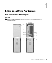
Setting Up and Using Your Computer Front and Back View of the Computer Front View NOTE: The front panel door does not close when you are using the Flash Media, IEEE 1394, USB, or headphone connectors. 12 11 10 1 2 9 8 3 7 6 5 4 Setting Up and Using Your Computer 13
Setting Up and Using Your Computer Front and Back View of the Computer Front View NOTE: The front panel door does not close when you are using the Flash Media, IEEE 1394, USB, or headphone connectors. 12 11 10 1 2 9 8 3 7 6 5 4 Setting Up and Using Your Computer 13
Owners Manual
Page 16
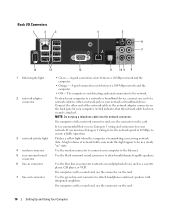
... amplifiers. Use the green line-out connector to attach headphones and most speakers with a sound card, use the connector on the card. Back I/O Connectors 1 2 3 4 5 6 7 14 13 12 11 10 9 8 1 link integrity light 2 network adapter connector 3 network activity light 4 modem connector 5 rear surround sound connector 6 line-in connector to attach a record/playback...
... amplifiers. Use the green line-out connector to attach headphones and most speakers with a sound card, use the connector on the card. Back I/O Connectors 1 2 3 4 5 6 7 14 13 12 11 10 9 8 1 link integrity light 2 network adapter connector 3 network activity light 4 modem connector 5 rear surround sound connector 6 line-in connector to attach a record/playback...
Owners Manual
Page 17
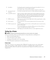
8 microphone 9 side surround sound connector 10 center/LFE connector 11 S/PDIF connector 12 VGA connector 13 USB 2.0 connectors (6) 14 IEEE 1394 connector Use the pink connector to provide extremely low bass extension. The LFE channel drives a subwoofer to attach a personal computer ...
8 microphone 9 side surround sound connector 10 center/LFE connector 11 S/PDIF connector 12 VGA connector 13 USB 2.0 connectors (6) 14 IEEE 1394 connector Use the pink connector to provide extremely low bass extension. The LFE channel drives a subwoofer to attach a personal computer ...
Owners Manual
Page 47
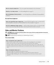
... monitor cable connectors to resume normal operation. The screen is blank CHECK THE MONITOR CABLE CONNECTION - • Ensure that the monitor is turned on page 13). R U N T H E S P E A K E R D I A G N O S T I N D O W S V O L U M E C O N T R O L - A D J U S T T H E W I C S - No sound from headphones C H E C K T H E H E A D P H O N E C A B L E C O N N E C T I V E R - R E I N S T A L L T H E S O U N D D R I O N - See "Resolving Software and Hardware Incompatibilities" on page 55...
... monitor cable connectors to resume normal operation. The screen is blank CHECK THE MONITOR CABLE CONNECTION - • Ensure that the monitor is turned on page 13). R U N T H E S P E A K E R D I A G N O S T I N D O W S V O L U M E C O N T R O L - A D J U S T T H E W I C S - No sound from headphones C H E C K T H E H E A D P H O N E C A B L E C O N N E C T I V E R - R E I N S T A L L T H E S O U N D D R I O N - See "Resolving Software and Hardware Incompatibilities" on page 55...
Owners Manual
Page 49
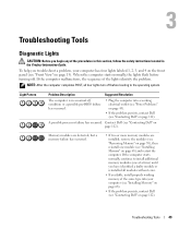
...install properly working electrical outlet (see "Power Problems" on page 43). • If the problem persists, contact Dell (see "Contacting Dell" on page 13). Light Pattern Problem Description Suggested Resolution The computer is in the Product Information Guide. A possible processor failure has...) until you troubleshoot a problem, your computer (see "Installing Memory" on page 68). • If the problem persists, contact Dell (see "Installing Memory" on page 112). When the computer starts normally, the lights flash before booting to install additional memory modules...
...install properly working electrical outlet (see "Power Problems" on page 43). • If the problem persists, contact Dell (see "Contacting Dell" on page 13). Light Pattern Problem Description Suggested Resolution The computer is in the Product Information Guide. A possible processor failure has...) until you troubleshoot a problem, your computer (see "Installing Memory" on page 68). • If the problem persists, contact Dell (see "Installing Memory" on page 112). When the computer starts normally, the lights flash before booting to install additional memory modules...
Owners Manual
Page 55
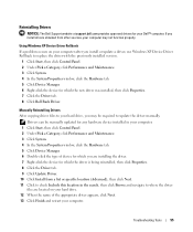
...your hard drive, you may not function properly. Reinstalling Drivers NOTICE: The Dell Support website at support.dell.com provides approved drivers for your computer may be manually updated for any ... 5 Click Device Manager. 6 Double-click the type of the appropriate driver appears, click Next. 13 Click Finish and restart your computer after you are installing the driver. 7 Right-click the device ...installed, then click Properties. 7 Click the Driver tab. 8 Click Roll Back Driver. Using Windows XP Device Driver Rollback If a problem occurs on your hard drive. 12 When the name of device...
...your hard drive, you may not function properly. Reinstalling Drivers NOTICE: The Dell Support website at support.dell.com provides approved drivers for your computer may be manually updated for any ... 5 Click Device Manager. 6 Double-click the type of the appropriate driver appears, click Next. 13 Click Finish and restart your computer after you are installing the driver. 7 Right-click the device ...installed, then click Properties. 7 Click the Driver tab. 8 Click Roll Back Driver. Using Windows XP Device Driver Rollback If a problem occurs on your hard drive. 12 When the name of device...
Owners Manual
Page 65
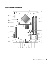
System Board Components 1 2 3 30 4 29 28 5 27 26 6 25 7 8 9 10 24 11 12 23 13 22 21 20 19 18 17 16 15 14 Removing and Installing Parts 65
System Board Components 1 2 3 30 4 29 28 5 27 26 6 25 7 8 9 10 24 11 12 23 13 22 21 20 19 18 17 16 15 14 Removing and Installing Parts 65
Owners Manual
Page 66
.../DVD connector (SATA1) 25 PCI Express x16 connector (SLOT1) 11 front-panel connector (FRONT PANEL) 26 standby LED (STBYLED) 12 modem 27 password jumper (CLRPSWD) 13 power connector (POWER) 28 RTC reset jumper (CLRCMOS) 14 line-in performance. NOTE: Buffered memory is not supported on the system board.
.../DVD connector (SATA1) 25 PCI Express x16 connector (SLOT1) 11 front-panel connector (FRONT PANEL) 26 standby LED (STBYLED) 12 modem 27 password jumper (CLRPSWD) 13 power connector (POWER) 28 RTC reset jumper (CLRCMOS) 14 line-in performance. NOTE: Buffered memory is not supported on the system board.
Owners Manual
Page 73
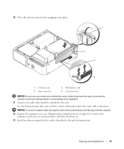
... plug the cable into the network device and then plug it into the computer. 12 Replace the computer cover (see "Replacing the Computer Cover" on . 13 Install any cables that came with the card for the card as described in the card documentation.
... plug the cable into the network device and then plug it into the computer. 12 Replace the computer cover (see "Replacing the Computer Cover" on . 13 Install any cables that came with the card for the card as described in the card documentation.

Owners Manual
Page 106
...you modify any boot sequence settings, save the new settings to boot from the CD drive. To make sure that your computer. 3 When the DELL logo appears, press immediately. To avoid possible keyboard failure, press and release in even intervals until you wait too long and the operating system logo... Drive - The computer attempts to wait until the Boot Device Menu appears. If you see "Front and Back View of the Computer" on page 13). 2 Turn on the screen when the computer starts. Boot Sequence This feature allows you are booting to a USB device, connect the USB device to...
...you modify any boot sequence settings, save the new settings to boot from the CD drive. To make sure that your computer. 3 When the DELL logo appears, press immediately. To avoid possible keyboard failure, press and release in even intervals until you wait too long and the operating system logo... Drive - The computer attempts to wait until the Boot Device Menu appears. If you see "Front and Back View of the Computer" on page 13). 2 Turn on the screen when the computer starts. Boot Sequence This feature allows you are booting to a USB device, connect the USB device to...

Owners Manual
Page 109
... the procedures in this section, follow the safety instructions located in the Product Information Guide. The password feature is enabled but a password is not assigned. 13 Assign a new system and/or administrator password, as Not Set. Clearing CMOS Settings CAUTION: Before you clean your computer and devices to electrical outlets, and...
... the procedures in this section, follow the safety instructions located in the Product Information Guide. The password feature is enabled but a password is not assigned. 13 Assign a new system and/or administrator password, as Not Set. Clearing CMOS Settings CAUTION: Before you clean your computer and devices to electrical outlets, and...
Owners Manual
Page 122
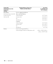
...(Milan) International Access Code: 00 Country Code: 39 City Code: 02 Jamaica Department Name or Service Area, Website and E-Mail Address Website: support.euro.dell.com Home and Small Business Technical Support Customer Care Fax Switchboard Corporate Technical Support Customer Care Fax Switchboard E-mail: la-techsupport...@dell.com Technical Support (dial from within Jamaica only) Area Codes, Local Numbers, and Toll-Free Numbers 02 577 826 90 02 696 821 14 02 696 821 13 02 696 821 12 02 577 826 90 02 577 825 ...
...(Milan) International Access Code: 00 Country Code: 39 City Code: 02 Jamaica Department Name or Service Area, Website and E-Mail Address Website: support.euro.dell.com Home and Small Business Technical Support Customer Care Fax Switchboard Corporate Technical Support Customer Care Fax Switchboard E-mail: la-techsupport...@dell.com Technical Support (dial from within Jamaica only) Area Codes, Local Numbers, and Toll-Free Numbers 02 577 826 90 02 696 821 14 02 696 821 13 02 696 821 12 02 577 826 90 02 577 825 ...


