Owners Manual
Page 3
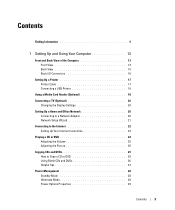
Contents Finding Information 9 1 Setting Up and Using Your Computer 13 Front and Back View of the Computer 13 Front View 13 Back View 15 Back I/O Connectors 16 Setting Up a Printer 17 Printer Cable 17 Connecting a USB Printer 18 Using a Media Card Reader (Optional 18 Connecting a TV (...
Contents Finding Information 9 1 Setting Up and Using Your Computer 13 Front and Back View of the Computer 13 Front View 13 Back View 15 Back I/O Connectors 16 Setting Up a Printer 17 Printer Cable 17 Connecting a USB Printer 18 Using a Media Card Reader (Optional 18 Connecting a TV (...
Owners Manual
Page 13
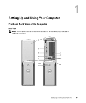
Setting Up and Using Your Computer Front and Back View of the Computer Front View NOTE: The front panel door does not close when you are using the Flash Media, IEEE 1394, USB, or headphone connectors. 12 11 10 1 2 9 8 3 7 6 5 4 Setting Up and Using Your Computer 13
Setting Up and Using Your Computer Front and Back View of the Computer Front View NOTE: The front panel door does not close when you are using the Flash Media, IEEE 1394, USB, or headphone connectors. 12 11 10 1 2 9 8 3 7 6 5 4 Setting Up and Using Your Computer 13
Owners Manual
Page 16
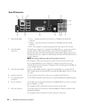
... connection exists between a 10-Mbps network and the computer. • Orange - On computers with a sound card, use the connector on the card. Back I/O Connectors 1 2 3 4 5 6 7 14 13 12 11 10 9 8 1 link integrity light 2 network adapter connector 3 network activity light 4 modem connector 5 rear surround sound connector 6 line-in connector to attach a record/playback...
... connection exists between a 10-Mbps network and the computer. • Orange - On computers with a sound card, use the connector on the card. Back I/O Connectors 1 2 3 4 5 6 7 14 13 12 11 10 9 8 1 link integrity light 2 network adapter connector 3 network activity light 4 modem connector 5 rear surround sound connector 6 line-in connector to attach a record/playback...
Owners Manual
Page 17
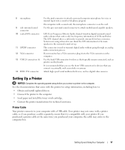
... at the same time you connect a printer to the computer. 8 microphone 9 side surround sound connector 10 center/LFE connector 11 S/PDIF connector 12 VGA connector 13 USB 2.0 connectors (6) 14 IEEE 1394 connector Use the pink connector to attach a personal computer microphone for devices that typically remain connected, such as digital video...
... at the same time you connect a printer to the computer. 8 microphone 9 side surround sound connector 10 center/LFE connector 11 S/PDIF connector 12 VGA connector 13 USB 2.0 connectors (6) 14 IEEE 1394 connector Use the pink connector to attach a personal computer microphone for devices that typically remain connected, such as digital video...
Owners Manual
Page 47
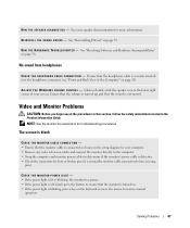
...-right corner of the Computer" on page 55. Click or double-click the speaker icon in the Product Information Guide. See "Reinstalling Drivers" on page 13). R U N T H E H A R D W A R E TR O U B L E S H O O T E R - NOTE: See the monitor documentation for monitor cable connectors to resume normal operation. Solving Problems 47 No sound from headphones C H E C K T H E H E A D P H O N E C A B L E C O N N E C T I N D O W S V O L U M E C O N T R O L - Ensure that the volume...
...-right corner of the Computer" on page 55. Click or double-click the speaker icon in the Product Information Guide. See "Reinstalling Drivers" on page 13). R U N T H E H A R D W A R E TR O U B L E S H O O T E R - NOTE: See the monitor documentation for monitor cable connectors to resume normal operation. Solving Problems 47 No sound from headphones C H E C K T H E H E A D P H O N E C A B L E C O N N E C T I N D O W S V O L U M E C O N T R O L - Ensure that the volume...
Owners Manual
Page 49
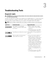
... troubleshoot a problem, your computer (see "Installing Memory" on page 68). • If the problem persists, contact Dell (see "Front View" on page 13). Troubleshooting Tools 49 When the computer starts normally, the lights flash before turning off before booting to install additional memory... modules (one module (see "Contacting Dell" on page 112). A possible processor failure has occurred. Troubleshooting Tools...
... troubleshoot a problem, your computer (see "Installing Memory" on page 68). • If the problem persists, contact Dell (see "Front View" on page 13). Troubleshooting Tools 49 When the computer starts normally, the lights flash before turning off before booting to install additional memory... modules (one module (see "Contacting Dell" on page 112). A possible processor failure has occurred. Troubleshooting Tools...
Owners Manual
Page 55
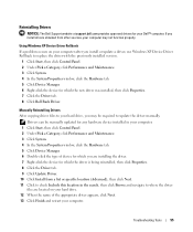
... click Next. 11 Click to check Include this location in the search, then click Browse and navigate to update the driver manually. Using Windows XP Device Driver Rollback If a problem occurs on your computer may be manually updated for any hardware device installed in your computer. 1 Click Start,... window, click the Hardware tab. 5 Click Device Manager. 6 Double-click the type of the appropriate driver appears, click Next. 13 Click Finish and restart your Dell™ computer. Drivers can be required to where the driver files are located on your hard drive. 12 When the name of ...
... click Next. 11 Click to check Include this location in the search, then click Browse and navigate to update the driver manually. Using Windows XP Device Driver Rollback If a problem occurs on your computer may be manually updated for any hardware device installed in your computer. 1 Click Start,... window, click the Hardware tab. 5 Click Device Manager. 6 Double-click the type of the appropriate driver appears, click Next. 13 Click Finish and restart your Dell™ computer. Drivers can be required to where the driver files are located on your hard drive. 12 When the name of ...
Owners Manual
Page 65
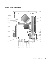
System Board Components 1 2 3 30 4 29 28 5 27 26 6 25 7 8 9 10 24 11 12 23 13 22 21 20 19 18 17 16 15 14 Removing and Installing Parts 65
System Board Components 1 2 3 30 4 29 28 5 27 26 6 25 7 8 9 10 24 11 12 23 13 22 21 20 19 18 17 16 15 14 Removing and Installing Parts 65
Owners Manual
Page 66
.../DVD connector (SATA1) 25 PCI Express x16 connector (SLOT1) 11 front-panel connector (FRONT PANEL) 26 standby LED (STBYLED) 12 modem 27 password jumper (CLRPSWD) 13 power connector (POWER) 28 RTC reset jumper (CLRCMOS) 14 line-in the order indicated on the system board. 66 Removing and Installing Parts
.../DVD connector (SATA1) 25 PCI Express x16 connector (SLOT1) 11 front-panel connector (FRONT PANEL) 26 standby LED (STBYLED) 12 modem 27 password jumper (CLRPSWD) 13 power connector (POWER) 28 RTC reset jumper (CLRCMOS) 14 line-in the order indicated on the system board. 66 Removing and Installing Parts
Owners Manual
Page 73
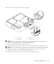
... plug the cable into the network device and then plug it into the computer. 12 Replace the computer cover (see "Replacing the Computer Cover" on . 13 Install any cables that came with the card for the card as described in the card documentation. 10 Close the card retention door by snapping...
... plug the cable into the network device and then plug it into the computer. 12 Replace the computer cover (see "Replacing the Computer Cover" on . 13 Install any cables that came with the card for the card as described in the card documentation. 10 Close the card retention door by snapping...

Owners Manual
Page 106
... corner of time. POST Hotkeys Keyboard Errors This option allows you see "Front and Back View of the Computer" on page 13). 2 Turn on (or restart) your computer. 3 When the DELL logo appears, press immediately. Option Settings • Diskette Drive - NOTE: To boot to change the boot sequence for extended periods of...
... corner of time. POST Hotkeys Keyboard Errors This option allows you see "Front and Back View of the Computer" on page 13). 2 Turn on (or restart) your computer. 3 When the DELL logo appears, press immediately. Option Settings • Diskette Drive - NOTE: To boot to change the boot sequence for extended periods of...

Owners Manual
Page 109
... (see "System Setup" on page 101), both system and administrator password options appear as needed. The password feature is enabled but a password is not assigned. 13 Assign a new system and/or administrator password, as Not Set. NOTICE: Do not wipe the display screen with water. NOTE: This procedure does not clear...
... (see "System Setup" on page 101), both system and administrator password options appear as needed. The password feature is enabled but a password is not assigned. 13 Assign a new system and/or administrator password, as Not Set. NOTICE: Do not wipe the display screen with water. NOTE: This procedure does not clear...
Owners Manual
Page 122
...(Milan) International Access Code: 00 Country Code: 39 City Code: 02 Jamaica Department Name or Service Area, Website and E-Mail Address Website: support.euro.dell.com Home and Small Business Technical Support Customer Care Fax Switchboard Corporate Technical Support Customer Care Fax Switchboard E-mail: la-techsupport...@dell.com Technical Support (dial from within Jamaica only) Area Codes, Local Numbers, and Toll-Free Numbers 02 577 826 90 02 696 821 14 02 696 821 13 02 696 821 12 02 577 826 90 02 577 825 ...
...(Milan) International Access Code: 00 Country Code: 39 City Code: 02 Jamaica Department Name or Service Area, Website and E-Mail Address Website: support.euro.dell.com Home and Small Business Technical Support Customer Care Fax Switchboard Corporate Technical Support Customer Care Fax Switchboard E-mail: la-techsupport...@dell.com Technical Support (dial from within Jamaica only) Area Codes, Local Numbers, and Toll-Free Numbers 02 577 826 90 02 696 821 14 02 696 821 13 02 696 821 12 02 577 826 90 02 577 825 ...


