Setup Guide
Page 20
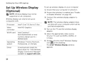
... the appropriate video source for "Intel Wireless Display Connection Manager" available at support.dell.com. Ensure that wireless is turned on all computers. NOTE: The wireless display adapter does not ship with : Processor Video controller WLAN card Operating system Intel® Core™ i3-3xx to ...the TV. Setting Up Your XPS Laptop Set Up Wireless Display (Optional) NOTE: Wireless display may not be supported on...
... the appropriate video source for "Intel Wireless Display Connection Manager" available at support.dell.com. Ensure that wireless is turned on all computers. NOTE: The wireless display adapter does not ship with : Processor Video controller WLAN card Operating system Intel® Core™ i3-3xx to ...the TV. Setting Up Your XPS Laptop Set Up Wireless Display (Optional) NOTE: Wireless display may not be supported on...
Setup Guide
Page 59
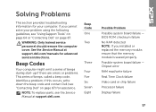
... information for assistance. If this occurs, write down the beep code and contact Dell (see "Contacting Dell" on page 87) for your problem using the following guidelines, see the Service Manual at support.dell.com/manuals for advanced service instructions. If you installed or replaced the memory module... page 87. Chipset error RAM read/write failure Real Time Clock failure Video card or chip failure Processor failure Display failure 57 See the Service Manual at support.dell.com. Beep Codes Your computer might emit a series of beeps during start-up if there are errors or ...
... information for assistance. If this occurs, write down the beep code and contact Dell (see "Contacting Dell" on page 87) for your problem using the following guidelines, see the Service Manual at support.dell.com/manuals for advanced service instructions. If you installed or replaced the memory module... page 87. Chipset error RAM read/write failure Real Time Clock failure Video card or chip failure Processor failure Display failure 57 See the Service Manual at support.dell.com. Beep Codes Your computer might emit a series of beeps during start-up if there are errors or ...
Setup Guide
Page 92
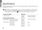
For more information regarding the configuration of your desktop. Computer Model Dell™ XPS™ L501X Computer Information System chipset Mobile Intel® 5 series express chipset HM57 Processor type Intel Core™ i3 Intel Core i5 Intel Core i7 Intel Pentium® 90 Memory Memory ... and 4 GB 2 GB 8 GB Specifications This section provides information that you may vary by region. To launch the Dell Support Center, click the icon in the Dell Support Center. NOTE: Offerings may need when setting up, updating drivers for, and upgrading your computer, see the About ...
For more information regarding the configuration of your desktop. Computer Model Dell™ XPS™ L501X Computer Information System chipset Mobile Intel® 5 series express chipset HM57 Processor type Intel Core™ i3 Intel Core i5 Intel Core i7 Intel Pentium® 90 Memory Memory ... and 4 GB 2 GB 8 GB Specifications This section provides information that you may vary by region. To launch the Dell Support Center, click the icon in the Dell Support Center. NOTE: Offerings may need when setting up, updating drivers for, and upgrading your computer, see the About ...

Service Manual
Page 7
Replacing the USB Board 88 20 TV Tuner Connector 91 Removing the TV Tuner Connector 91 Replacing the TV Tuner Connector 92 21 Heat Sink 95 Removing the Heat Sink 95 Replacing the Heat Sink 96 22 Processor Module 99 Removing the Processor Module 99 Replacing the Processor Module 101 23 System Board 103 Removing the System Board 103 Replacing the System Board 105 Entering the Service Tag in the BIOS 106 24 Speakers 109 Removing the Speakers 109 Replacing the Speakers 110 Contents 7
Replacing the USB Board 88 20 TV Tuner Connector 91 Removing the TV Tuner Connector 91 Replacing the TV Tuner Connector 92 21 Heat Sink 95 Removing the Heat Sink 95 Replacing the Heat Sink 96 22 Processor Module 99 Removing the Processor Module 99 Replacing the Processor Module 101 23 System Board 103 Removing the System Board 103 Replacing the System Board 105 Entering the Service Tag in the BIOS 106 24 Speakers 109 Removing the Speakers 109 Replacing the Speakers 110 Contents 7

Service Manual
Page 10
.... CAUTION: To avoid electrostatic discharge, ground yourself by using a wrist grounding strap or by periodically touching an unpainted metal surface (such as a processor by its edges, not by its pins. CAUTION: When you disconnect a cable, pull on its connector or on page 9) and all attached ... the cable. Hold a component such as a connector on the locking tabs before you connect a cable, ensure that is not authorized by Dell™ is flat and clean to avoid bending any installed cards from being scratched. 2 Turn off your computer (see the Regulatory Compliance Homepage...
.... CAUTION: To avoid electrostatic discharge, ground yourself by using a wrist grounding strap or by periodically touching an unpainted metal surface (such as a processor by its edges, not by its pins. CAUTION: When you disconnect a cable, pull on its connector or on page 9) and all attached ... the cable. Hold a component such as a connector on the locking tabs before you connect a cable, ensure that is not authorized by Dell™ is flat and clean to avoid bending any installed cards from being scratched. 2 Turn off your computer (see the Regulatory Compliance Homepage...

Service Manual
Page 71
... should perform repairs on your computer. CAUTION: To avoid electrostatic discharge, ground yourself by using a wrist grounding strap or by your computer. Processor Fan 71 CAUTION: To help prevent damage to step 14 in "Before You Begin" on page 9. 2 Press and eject any installed cards... 49). 9 Follow the instructions from step 9 to the system board, remove the main battery (see the Regulatory Compliance Homepage at www.dell.com/regulatory_compliance. For additional safety best practices information, see "Removing the Battery" on page 65. 10 Remove the two screws that is ...
... should perform repairs on your computer. CAUTION: To avoid electrostatic discharge, ground yourself by using a wrist grounding strap or by your computer. Processor Fan 71 CAUTION: To help prevent damage to step 14 in "Before You Begin" on page 9. 2 Press and eject any installed cards... 49). 9 Follow the instructions from step 9 to the system board, remove the main battery (see the Regulatory Compliance Homepage at www.dell.com/regulatory_compliance. For additional safety best practices information, see "Removing the Battery" on page 65. 10 Remove the two screws that is ...

Service Manual
Page 72
Replacing the Fan 1 Follow the instructions in "Before You Begin" on page 9. 2 Place the fan on the base cover. 3 Replace the two screws that secure the fan to the base cover. 4 Follow the instructions from step 9 to step 12 in "Replacing the Top Cover" on page 69. 5 Replace the display assembly (see "Replacing the Display Assembly" on page 52). 6 Replace the keyboard (see "Replacing the Keyboard" on page 46). 72 Processor Fan 1 2 1 screws (2) 2 fan 11 Lift the fan off the base cover.
Replacing the Fan 1 Follow the instructions in "Before You Begin" on page 9. 2 Place the fan on the base cover. 3 Replace the two screws that secure the fan to the base cover. 4 Follow the instructions from step 9 to step 12 in "Replacing the Top Cover" on page 69. 5 Replace the display assembly (see "Replacing the Display Assembly" on page 52). 6 Replace the keyboard (see "Replacing the Keyboard" on page 46). 72 Processor Fan 1 2 1 screws (2) 2 fan 11 Lift the fan off the base cover.

Service Manual
Page 73
Processor Fan 73 Failure to do so may result in damage to the computer. 7 Replace the palm-rest assembly (see "Replacing the Palm-Rest Assembly" on page 32). 8 Replace the memory module(s) (see "Replacing the Memory Module(s)" on page 18). 9 Replace the module cover (see "Replacing the Module Cover" on page 16). 10 Replace the battery (see "Replacing the Battery" on the computer, replace all screws and ensure that no stray screws remain inside the computer. CAUTION: Before turning on page 14).
Processor Fan 73 Failure to do so may result in damage to the computer. 7 Replace the palm-rest assembly (see "Replacing the Palm-Rest Assembly" on page 32). 8 Replace the memory module(s) (see "Replacing the Memory Module(s)" on page 18). 9 Replace the module cover (see "Replacing the Module Cover" on page 16). 10 Replace the battery (see "Replacing the Battery" on the computer, replace all screws and ensure that no stray screws remain inside the computer. CAUTION: Before turning on page 14).

Service Manual
Page 96
Replacing the Heat Sink NOTE: The original thermal grease can be reused if the original processor and heat sink are reinstalled together. 9 In sequential order (indicated on the heat sink), loosen the seven captive screws that secure the heat sink to ... system board and tighten the screws in "Replacing the Top Cover" on the heat sink). 4 Follow the instructions from the top cover. If either the processor or the heat sink is replaced, use the thermal pad provided in the kit to step 12 in sequential order (indicated on page 69. 96...
Replacing the Heat Sink NOTE: The original thermal grease can be reused if the original processor and heat sink are reinstalled together. 9 In sequential order (indicated on the heat sink), loosen the seven captive screws that secure the heat sink to ... system board and tighten the screws in "Replacing the Top Cover" on the heat sink). 4 Follow the instructions from the top cover. If either the processor or the heat sink is replaced, use the thermal pad provided in the kit to step 12 in sequential order (indicated on page 69. 96...

Service Manual
Page 99
... information, see "Removing the Heat Sink" on page 65. 9 Remove the heat sink (see the Regulatory Compliance Homepage at www.dell.com/regulatory_compliance. Removing the Processor Module 1 Follow the instructions in "Before You Begin" on page 9. 2 Remove the battery (see "Removing the Battery" on page... step 9 to step 14 in "Removing the Top Cover" on page 95). 22 Processor Module WARNING: Before working inside your computer, read the safety information that is not authorized by Dell™ is not covered by periodically touching an unpainted metal surface (such as a connector...
... information, see "Removing the Heat Sink" on page 65. 9 Remove the heat sink (see the Regulatory Compliance Homepage at www.dell.com/regulatory_compliance. Removing the Processor Module 1 Follow the instructions in "Before You Begin" on page 9. 2 Remove the battery (see "Removing the Battery" on page... step 9 to step 14 in "Removing the Top Cover" on page 95). 22 Processor Module WARNING: Before working inside your computer, read the safety information that is not authorized by Dell™ is not covered by periodically touching an unpainted metal surface (such as a connector...

Service Manual
Page 100
...ZIF-socket cam screw counterclockwise until it comes to the centre of the thermal pads. 100 Processor Module The oils in your skin can reduce the heat transfer capability of the processor while turning the cam screw. CAUTION: To prevent intermittent contact between the ZIF-socket cam... screw and the processor when removing or replacing the processor, press to apply slight pressure to the cam stop. 4 1 2 3 1 ZIF socket 3 pin-1 corner 2 processor module 4 ZIF-socket cam screw CAUTION: To ensure maximum cooling for the processor module, do not touch the heat transfer...
...ZIF-socket cam screw counterclockwise until it comes to the centre of the thermal pads. 100 Processor Module The oils in your skin can reduce the heat transfer capability of the processor while turning the cam screw. CAUTION: To prevent intermittent contact between the ZIF-socket cam... screw and the processor when removing or replacing the processor, press to apply slight pressure to the cam stop. 4 1 2 3 1 ZIF socket 3 pin-1 corner 2 processor module 4 ZIF-socket cam screw CAUTION: To ensure maximum cooling for the processor module, do not touch the heat transfer...

Service Manual
Page 101
... the Heat Sink" on page 96). 6 Follow the instructions from step 9 to bend the pins on the processor module. 11 Lift the processor module off the ZIF socket. NOTE: The pin-1 corner of the processor module has a triangle that aligns with the triangle on the pin-1 corner of the ZIF socket. 3 Place the... cover (see "Replacing the Module Cover" on page 16). 12 Replace the battery (see "Replacing the Battery" on page 9. 2 Align the pin-1 corner of the processor module with the pin-1 corner of the ZIF socket. Be careful not to step 12 in "Before You Begin" on page 14...
... the Heat Sink" on page 96). 6 Follow the instructions from step 9 to bend the pins on the processor module. 11 Lift the processor module off the ZIF socket. NOTE: The pin-1 corner of the processor module has a triangle that aligns with the triangle on the pin-1 corner of the ZIF socket. 3 Place the... cover (see "Replacing the Module Cover" on page 16). 12 Replace the battery (see "Replacing the Battery" on page 9. 2 Align the pin-1 corner of the processor module with the pin-1 corner of the ZIF socket. Be careful not to step 12 in "Before You Begin" on page 14...

Service Manual
Page 102
CAUTION: Before turning on the computer, replace all screws and ensure that no stray screws remain inside the computer. Failure to do so may result in damage to the computer. 102 Processor Module
CAUTION: Before turning on the computer, replace all screws and ensure that no stray screws remain inside the computer. Failure to do so may result in damage to the computer. 102 Processor Module

Service Manual
Page 104
9 Disconnect the USB board cable and speaker cable from the connectors on the system board. 1 2 1 USB board cable connector 2 speaker cable connector 10 Turn the top cover over. 11 Remove the heat sink (see "Removing the Heat Sink" on page 95). 12 Remove the processor module (see "Removing the Processor Module" on page 99). 13 Disconnect the Bluetooth cable and AC-adapter cable from the connector on the system board. 14 Remove the five screws that secure the system board to the top cover. 104 System Board
9 Disconnect the USB board cable and speaker cable from the connectors on the system board. 1 2 1 USB board cable connector 2 speaker cable connector 10 Turn the top cover over. 11 Remove the heat sink (see "Removing the Heat Sink" on page 95). 12 Remove the processor module (see "Removing the Processor Module" on page 99). 13 Disconnect the Bluetooth cable and AC-adapter cable from the connector on the system board. 14 Remove the five screws that secure the system board to the top cover. 104 System Board

Service Manual
Page 106
... "Replacing the Battery" on page 14). 4 Connect the Bluetooth cable and AC-adapter cable to the connectors on the system board. 5 Replace the processor module (see "Replacing the Processor Module" on page 101). 6 Replace the heat sink (see "Replacing the Heat Sink" on page 96). 7 Turn the top cover over and connect...
... "Replacing the Battery" on page 14). 4 Connect the Bluetooth cable and AC-adapter cable to the connectors on the system board. 5 Replace the processor module (see "Replacing the Processor Module" on page 101). 6 Replace the heat sink (see "Replacing the Heat Sink" on page 96). 7 Turn the top cover over and connect...


