Specifications
Page 5
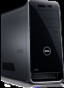
Views Dimensions and weight Height Width Depth Weight (maximum) Specifications 406.80 mm (16 in) 185.34 mm (7.3 in) 444.26 mm (17.5 in) 13.3 kg (29.3 lb) NOTE: The weight of your desktop varies depending on the configuration ordered and the manufacturing variability. Dimensions and weight System information Memory Ports and connectors Communications Video Media-card reader Power ratings Computer environment Audio Storage
Views Dimensions and weight Height Width Depth Weight (maximum) Specifications 406.80 mm (16 in) 185.34 mm (7.3 in) 444.26 mm (17.5 in) 13.3 kg (29.3 lb) NOTE: The weight of your desktop varies depending on the configuration ordered and the manufacturing variability. Dimensions and weight System information Memory Ports and connectors Communications Video Media-card reader Power ratings Computer environment Audio Storage
Specifications
Page 6
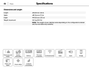
Views System information Computer model Processor Chipset Specifications XPS 8900 • 6th Generation Intel Core i5 Processor • 6th Generation Intel Core i7 Processor Intel Z170 Dimensions and weight System information Memory Ports and connectors Communications Video Media-card reader Power ratings Computer environment Audio Storage
Views System information Computer model Processor Chipset Specifications XPS 8900 • 6th Generation Intel Core i5 Processor • 6th Generation Intel Core i7 Processor Intel Z170 Dimensions and weight System information Memory Ports and connectors Communications Video Media-card reader Power ratings Computer environment Audio Storage

Specifications
Page 7
Views Memory Slot Type Speed Configurations supported Specifications Four DIMM slots DDR4 2133 MHz 8 GB, 16 GB, 24 GB, and 32 GB Dimensions and weight System information Memory Ports and connectors Communications Video Media-card reader Power ratings Computer environment Audio Storage
Views Memory Slot Type Speed Configurations supported Specifications Four DIMM slots DDR4 2133 MHz 8 GB, 16 GB, 24 GB, and 32 GB Dimensions and weight System information Memory Ports and connectors Communications Video Media-card reader Power ratings Computer environment Audio Storage

Specifications
Page 8
... • One PCIe x4 card slot • One PCIe x16 card slot • One PCIe x16 card slot (x4 wire) Dimensions and weight System information Memory Ports and connectors Communications Video Media-card reader Power ratings Computer environment Audio Storage
... • One PCIe x4 card slot • One PCIe x16 card slot • One PCIe x16 card slot (x4 wire) Dimensions and weight System information Memory Ports and connectors Communications Video Media-card reader Power ratings Computer environment Audio Storage

Specifications
Page 9
Views Communications Ethernet Wireless Specifications 10/100/1000 Mbps Ethernet controller integrated on system board • Wi-Fi 802.11b/g/n • Wi-Fi 802.11ac • Bluetooth 4.0 Dimensions and weight System information Memory Ports and connectors Communications Video Media-card reader Power ratings Computer environment Audio Storage
Views Communications Ethernet Wireless Specifications 10/100/1000 Mbps Ethernet controller integrated on system board • Wi-Fi 802.11b/g/n • Wi-Fi 802.11ac • Bluetooth 4.0 Dimensions and weight System information Memory Ports and connectors Communications Video Media-card reader Power ratings Computer environment Audio Storage

Specifications
Page 10
Views Video Controller: Integrated Discrete Memory: Integrated Discrete Specifications Intel HD Graphics 530 • NVIDIA GT 730 • NVIDIA GTX 745 • NVIDIA GTX 750 Ti • NVIDIA GTX 960 • AMD Radeon R9 370 Shared system memory Up to 4 GB GDDR5 Dimensions and weight System information Memory Ports and connectors Communications Video Media-card reader Power ratings Computer environment Audio Storage
Views Video Controller: Integrated Discrete Memory: Integrated Discrete Specifications Intel HD Graphics 530 • NVIDIA GT 730 • NVIDIA GTX 745 • NVIDIA GTX 750 Ti • NVIDIA GTX 960 • AMD Radeon R9 370 Shared system memory Up to 4 GB GDDR5 Dimensions and weight System information Memory Ports and connectors Communications Video Media-card reader Power ratings Computer environment Audio Storage

Specifications
Page 11
Views Audio Controller Specifications Integrated 7.1 channel Realtek ALC3861 High Definition Audio with Waves MaxxAudio Pro Dimensions and weight System information Memory Ports and connectors Communications Video Media-card reader Power ratings Computer environment Audio Storage
Views Audio Controller Specifications Integrated 7.1 channel Realtek ALC3861 High Definition Audio with Waves MaxxAudio Pro Dimensions and weight System information Memory Ports and connectors Communications Video Media-card reader Power ratings Computer environment Audio Storage

Specifications
Page 12
Views Storage Interface Hard drives Solid-state drive (SSD) Optical drive (optional) Specifications • SATA 3 Gbps for optical drive • SATA 6 Gbps for hard drive • M.2 for SSD Three 3.5-inch hard drives One M.2 slot Two 5.25-inch DVD+/-RW and Blu-ray disc writer Dimensions and weight System information Memory Ports and connectors Communications Video Media-card reader Power ratings Computer environment Audio Storage
Views Storage Interface Hard drives Solid-state drive (SSD) Optical drive (optional) Specifications • SATA 3 Gbps for optical drive • SATA 6 Gbps for hard drive • M.2 for SSD Three 3.5-inch hard drives One M.2 slot Two 5.25-inch DVD+/-RW and Blu-ray disc writer Dimensions and weight System information Memory Ports and connectors Communications Video Media-card reader Power ratings Computer environment Audio Storage

Specifications
Page 15
... drive is in use. ‡ Measured using a 2 ms half-sine pulse when the hard-drive head is in parked position. Dimensions and weight System information Memory Ports and connectors Communications Video Media-card reader Power ratings Computer environment Audio Storage
... drive is in use. ‡ Measured using a 2 ms half-sine pulse when the hard-drive head is in parked position. Dimensions and weight System information Memory Ports and connectors Communications Video Media-card reader Power ratings Computer environment Audio Storage
Service Manual
Page 3
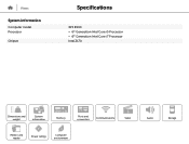
Contents Before working inside your computer 11 Before you begin 11 Safety instructions 11 Recommended tools 12 After working inside your computer 14 Technical overview 15 Inside view of your computer 15 System-board components 16 Removing the computer cover 18 Procedure...18 Replacing the computer cover 19 Procedure...19 Post-requisites 19 Removing the memory modules 20 Prerequisites...20 Procedure...20 Replacing the memory modules 22 Procedure...22 Post-requisites 23 Removing the chassis fan 24 Prerequisites...24 Procedure...24 3
Contents Before working inside your computer 11 Before you begin 11 Safety instructions 11 Recommended tools 12 After working inside your computer 14 Technical overview 15 Inside view of your computer 15 System-board components 16 Removing the computer cover 18 Procedure...18 Replacing the computer cover 19 Procedure...19 Post-requisites 19 Removing the memory modules 20 Prerequisites...20 Procedure...20 Replacing the memory modules 22 Procedure...22 Post-requisites 23 Removing the chassis fan 24 Prerequisites...24 Procedure...24 3
Service Manual
Page 16
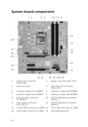
System-board components 1 chassis-fan connector (FAN_SYS2) 2 power connector (ATX_CPU) 3 processor cover 4 processor-fan connector (FAN_CPU) 5 memory-module slot (DIMM3) 6 memory-module slot (DIMM1) 7 memory-module slot (DIMM4) 8 memory-module slot (DIMM2) 9 power-button connector (F_PANEL1) 10 SATA 6 Gbps drive connector (SATA 1) 11 main-power connector (ATX_SYS_2) 12 SATA 6 Gbps drive connector (SATA 2) 13 Front2-USB connector (F_USB4) 14 Front-USB connector (F_USB3) 15 Front-USB connector (F_USB2) 16 solid-state drive slot 16
System-board components 1 chassis-fan connector (FAN_SYS2) 2 power connector (ATX_CPU) 3 processor cover 4 processor-fan connector (FAN_CPU) 5 memory-module slot (DIMM3) 6 memory-module slot (DIMM1) 7 memory-module slot (DIMM4) 8 memory-module slot (DIMM2) 9 power-button connector (F_PANEL1) 10 SATA 6 Gbps drive connector (SATA 1) 11 main-power connector (ATX_SYS_2) 12 SATA 6 Gbps drive connector (SATA 2) 13 Front2-USB connector (F_USB4) 14 Front-USB connector (F_USB3) 15 Front-USB connector (F_USB2) 16 solid-state drive slot 16
Service Manual
Page 20
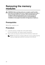
...follow the instructions in Before working inside your computer. Prerequisites Remove the computer cover. NOTE: If the memory module is difficult to remove, gently ease the memory module back and forth to remove it from the slot. 20 For more information, see the Regulatory Compliance... home page at each end of the memory-module slot. For more safety best practices, see "System-board components". 2 Press out the securing clip at www.dell.com/regulatory_compliance. After working inside your computer, follow the steps in After ...
...follow the instructions in Before working inside your computer. Prerequisites Remove the computer cover. NOTE: If the memory module is difficult to remove, gently ease the memory module back and forth to remove it from the slot. 20 For more information, see the Regulatory Compliance... home page at each end of the memory-module slot. For more safety best practices, see "System-board components". 2 Press out the securing clip at www.dell.com/regulatory_compliance. After working inside your computer, follow the steps in After ...

Service Manual
Page 21
3 Remove the memory module out of the memory-module slot. 1 securing clips (2) 3 memory module 2 memory-module slot 21
3 Remove the memory module out of the memory-module slot. 1 securing clips (2) 3 memory module 2 memory-module slot 21

Service Manual
Page 22
After working inside your computer, follow the steps in After working inside your computer. For more safety best practices, see the Regulatory Compliance home page at www.dell.com/regulatory_compliance. Procedure 1 Align the notch on the memory module with your computer and follow the instructions in Before working inside your computer. Replacing the memory modules WARNING: Before working inside your computer, read the safety information that shipped with the tab on the memorymodule slot. 22
After working inside your computer, follow the steps in After working inside your computer. For more safety best practices, see the Regulatory Compliance home page at www.dell.com/regulatory_compliance. Procedure 1 Align the notch on the memory module with your computer and follow the instructions in Before working inside your computer. Replacing the memory modules WARNING: Before working inside your computer, read the safety information that shipped with the tab on the memorymodule slot. 22

Service Manual
Page 23
2 Insert the memory module into the memory-module slot, and press the memory module down until it . 1 securing clips (2) 3 memory-module slot Post-requisites Replace the computer cover. 2 memory module 4 notch 23 NOTE: If you do not hear the click, remove the memory module and reinstall it snaps into position and the securing clips lock in place.
2 Insert the memory module into the memory-module slot, and press the memory module down until it . 1 securing clips (2) 3 memory-module slot Post-requisites Replace the computer cover. 2 memory module 4 notch 23 NOTE: If you do not hear the click, remove the memory module and reinstall it snaps into position and the securing clips lock in place.
Service Manual
Page 97
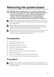
... stored in the BIOS setup program after you replace the system board. Prerequisites 1 Remove the computer cover. 2 Remove the wireless card. 3 Remove the memory modules. 4 Remove the graphics-card bracket. 5 Remove the graphics card. 6 Remove the processor fan and heat sink assembly. 7 Remove the processor....reconnect the cables correctly after you replace the system board. 97 For more information, see the Regulatory Compliance home page at www.dell.com/regulatory_compliance. NOTE: Your computer's Service Tag is stored in the BIOS setup program after you have made to the system ...
... stored in the BIOS setup program after you replace the system board. Prerequisites 1 Remove the computer cover. 2 Remove the wireless card. 3 Remove the memory modules. 4 Remove the graphics-card bracket. 5 Remove the graphics card. 6 Remove the processor fan and heat sink assembly. 7 Remove the processor....reconnect the cables correctly after you replace the system board. 97 For more information, see the Regulatory Compliance home page at www.dell.com/regulatory_compliance. NOTE: Your computer's Service Tag is stored in the BIOS setup program after you have made to the system ...

Service Manual
Page 99
... working inside your computer. For more information, see the Regulatory Compliance home page at www.dell.com/regulatory_compliance. Post-requisites 1 Replacing the processor. 2 Replacing the processor fan and heat sink assembly. 3 Remove the graphics card. 4 Replacing the memory modules. 5 Replacing the wireless card. 6 Replacing the computer cover. 99 NOTE: Replacing the system...
... working inside your computer. For more information, see the Regulatory Compliance home page at www.dell.com/regulatory_compliance. Post-requisites 1 Replacing the processor. 2 Replacing the processor fan and heat sink assembly. 3 Remove the graphics card. 4 Replacing the memory modules. 5 Replacing the wireless card. 6 Replacing the computer cover. 99 NOTE: Replacing the system...


