Owner's Manual
Page 6
... a Dual Configuration . . . . . 102 Network Adapter and Sound Card Settings 105 Drives 106 About Serial ATA Drives 107 General Drive Installation Guidelines 107 Hard Drive 108 Removing a Hard Drive 108 Installing a Hard Drive 110 Drive Panel 113 Removing the Drive Panel 113 Replacing the Drive Panel 114 Floppy Drive 115 Removing a Floppy Drive 115 Installing a Floppy Drive 117 Media Card Reader 119 Removing a Media Card Reader 119...
... a Dual Configuration . . . . . 102 Network Adapter and Sound Card Settings 105 Drives 106 About Serial ATA Drives 107 General Drive Installation Guidelines 107 Hard Drive 108 Removing a Hard Drive 108 Installing a Hard Drive 110 Drive Panel 113 Removing the Drive Panel 113 Replacing the Drive Panel 114 Floppy Drive 115 Removing a Floppy Drive 115 Installing a Floppy Drive 117 Media Card Reader 119 Removing a Media Card Reader 119...
Owner's Manual
Page 7
Removing the Optional Hard Drive Fan 137 Installing the Optional Hard Drive Fan 138 System Board 139 Removing the System Board 139 Installing the System Board 140 Power Supply 141 Power Supply (PSU) DC Connector Pin Assignments ... Power Supply 154 Front I/O Panel 155 Front I/O-Panel Components 155 Removing the Front I/O Panel 156 Installing the I/O Panel 157 Battery 157 Replacing the Battery 157 Removing the Computer Stand 158 Replacing the Computer Cover 159 6 Appendix 161 Specifications 161 System Setup 166 Overview 166 Entering System Setup 166 System Setup Options 167...
Removing the Optional Hard Drive Fan 137 Installing the Optional Hard Drive Fan 138 System Board 139 Removing the System Board 139 Installing the System Board 140 Power Supply 141 Power Supply (PSU) DC Connector Pin Assignments ... Power Supply 154 Front I/O Panel 155 Front I/O-Panel Components 155 Removing the Front I/O Panel 156 Installing the I/O Panel 157 Battery 157 Replacing the Battery 157 Removing the Computer Stand 158 Replacing the Computer Cover 159 6 Appendix 161 Specifications 161 System Setup 166 Overview 166 Entering System Setup 166 System Setup Options 167...

Owner's Manual
Page 30
... 1 mirror by the number of two drives. 30 Setting Up and Using Your Computer When data is equal to the size of the drives. A replacement drive can then be rebuilt using the data from the surviving drive. NOTE: In a RAID level 0 configuration..., the size of the configuration is written to the surviving drive. RAID Level 1 Configuration RAID level 1 uses a data-redundancy storage technique known as "mirroring" to store data. For example, two 120-GB hard drives...
... 1 mirror by the number of two drives. 30 Setting Up and Using Your Computer When data is equal to the size of the drives. A replacement drive can then be rebuilt using the data from the surviving drive. NOTE: In a RAID level 0 configuration..., the size of the configuration is written to the surviving drive. RAID Level 1 Configuration RAID level 1 uses a data-redundancy storage technique known as "mirroring" to store data. For example, two 120-GB hard drives...

Owner's Manual
Page 32
... array). Both methods require that you set your computer to store data. If a drive failure occurs, subsequent read and write operations are directed to configure RAID hard drive volumes. A replacement drive can then be configured for RAID Your computer can use one of the most popular ...implementations of 360-GB on the primary and additional drives, four 120-GB RAID level 1 drives collectively have installed the operating system...
... array). Both methods require that you set your computer to store data. If a drive failure occurs, subsequent read and write operations are directed to configure RAID hard drive volumes. A replacement drive can then be configured for RAID Your computer can use one of the most popular ...implementations of 360-GB on the primary and additional drives, four 120-GB RAID level 1 drives collectively have installed the operating system...

Owner's Manual
Page 36
...Setting Your Computer to RAID-Enabled Mode" on the selected drives in the next step. 7 Under Free Disk Selection, select the hard drive(s) you want to include in the (migrated) array by restoring the data to a replacement drive. The NVIDIA Rebuild Array Wizard appears. 36 Setting Up... and Using Your Computer If needed, additional hard drives can only be performed using the migrating process. NVIDIA MediaShield utilizes a one of the hard drives in a RAID array fails, you ...
...Setting Your Computer to RAID-Enabled Mode" on the selected drives in the next step. 7 Under Free Disk Selection, select the hard drive(s) you want to include in the (migrated) array by restoring the data to a replacement drive. The NVIDIA Rebuild Array Wizard appears. 36 Setting Up... and Using Your Computer If needed, additional hard drives can only be performed using the migrating process. NVIDIA MediaShield utilizes a one of the hard drives in a RAID array fails, you ...
Owner's Manual
Page 71
...An interrupt channel on drive A or drive C. Check the interface cable at both ends. The operating system cannot be replaced. Ensure that drive A or drive C is properly identified. The keyboard or system board may need to POST. Troubleshooting 71 Corrective Action See "Contacting Dell" on page 179 for... system setup program (see "System Setup" on page 166). The BIOS cannot communicate with the floppy drive or hard drive controller. Ensure that the floppy drive or the hard drive is installed correctly in the computer (see "System Setup" on page 166) and confirm that the...
...An interrupt channel on drive A or drive C. Check the interface cable at both ends. The operating system cannot be replaced. Ensure that drive A or drive C is properly identified. The keyboard or system board may need to POST. Troubleshooting 71 Corrective Action See "Contacting Dell" on page 179 for... system setup program (see "System Setup" on page 166). The BIOS cannot communicate with the floppy drive or hard drive controller. Ensure that the floppy drive or the hard drive is installed correctly in the computer (see "System Setup" on page 166) and confirm that the...
Owner's Manual
Page 72
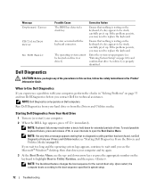
...At the Boot Device Menu, use the up . Dell Diagnostics CAUTION: Before you contact Dell for the current boot only. Starting Dell Diagnostics From Your Hard Drive 1 Turn on page 73). if a key appears to Use Dell Diagnostics If you may need to replace the keyboard. NOTE: If at any of time... Setup" on page 166) and confirm that no diagnostics utility partition has been found, run Dell Diagnostics from your hard drive or from your Drivers and Utilities media (see "Starting Dell Diagnostics From the Drivers and Utilities Media" on (or restart) your computer, perform the checks...
...At the Boot Device Menu, use the up . Dell Diagnostics CAUTION: Before you contact Dell for the current boot only. Starting Dell Diagnostics From Your Hard Drive 1 Turn on page 73). if a key appears to Use Dell Diagnostics If you may need to replace the keyboard. NOTE: If at any of time... Setup" on page 166) and confirm that no diagnostics utility partition has been found, run Dell Diagnostics from your hard drive or from your Drivers and Utilities media (see "Starting Dell Diagnostics From the Drivers and Utilities Media" on (or restart) your computer, perform the checks...

Owner's Manual
Page 106
... you installed an add-in network adapter connectors. Drives Your computer supports: • Six SATA devices (hard drives or optical drives) • Two IDE devices (two hard drives or two optical drives) • One floppy drive • One Media Card Reader NOTICE: When removing and replacing drives, be sure to leave the drive data and power cables connected to the integrated...
... you installed an add-in network adapter connectors. Drives Your computer supports: • Six SATA devices (hard drives or optical drives) • Two IDE devices (two hard drives or two optical drives) • One floppy drive • One Media Card Reader NOTICE: When removing and replacing drives, be sure to leave the drive data and power cables connected to the integrated...

Owner's Manual
Page 108
...electrical outlet before you want to the middle connector on page 86). 3 Disconnect the power cable and the data cable from the hard drive. 108 Removing and Installing Parts To connect an IDE data cable, align the tab on one connector with the notch on configuring ...is the secondary device. CAUTION: To guard against electrical shock, always unplug your files before removing the cover. NOTICE: If you are replacing a hard drive that contains data that you begin any of the procedures in this procedure. 1 Follow the procedures in the Product Information Guide. When disconnecting...
...electrical outlet before you want to the middle connector on page 86). 3 Disconnect the power cable and the data cable from the hard drive. 108 Removing and Installing Parts To connect an IDE data cable, align the tab on one connector with the notch on configuring ...is the secondary device. CAUTION: To guard against electrical shock, always unplug your files before removing the cover. NOTICE: If you are replacing a hard drive that contains data that you begin any of the procedures in this procedure. 1 Follow the procedures in the Product Information Guide. When disconnecting...

Owner's Manual
Page 110
...hard drive 3 hard drive bay 5 Ensure that all connectors are properly cabled and firmly seated. 6 Replace the computer cover (see "Removing a Hard Drive" on page 108). Installing a Hard Drive CAUTION: Before you begin any of the hard drive bay, remove the bracket before you install the new hard drive. 110 Removing and Installing Parts NOTE: If a hard drive...Remove the computer cover (see "Removing the Computer Cover" on page 86). 3 Remove the existing hard drive, if applicable (see "Replacing the Computer Cover" on . NOTICE: To connect a network cable, first plug the cable into the...
...hard drive 3 hard drive bay 5 Ensure that all connectors are properly cabled and firmly seated. 6 Replace the computer cover (see "Removing a Hard Drive" on page 108). Installing a Hard Drive CAUTION: Before you begin any of the hard drive bay, remove the bracket before you install the new hard drive. 110 Removing and Installing Parts NOTE: If a hard drive...Remove the computer cover (see "Removing the Computer Cover" on page 86). 3 Remove the existing hard drive, if applicable (see "Replacing the Computer Cover" on . NOTICE: To connect a network cable, first plug the cable into the...

Owner's Manual
Page 137
... board (see "System Board Components" on page 89). 4 Replace the computer cover (see "System Board Components" on page 89). 5 Press the release latch on the hard drive fan and slide it out from between the hard drive bays, then lift it from the FAN_HDD connector on the system... board (see "Replacing the Computer Cover" on page 159). 3 2 1 1 rubber grommet (4) 2 CPU fan 3 processor airflow shroud 2 Replace the processor airflow shroud (see...
... board (see "System Board Components" on page 89). 4 Replace the computer cover (see "System Board Components" on page 89). 5 Press the release latch on the hard drive fan and slide it out from between the hard drive bays, then lift it from the FAN_HDD connector on the system... board (see "Replacing the Computer Cover" on page 159). 3 2 1 1 rubber grommet (4) 2 CPU fan 3 processor airflow shroud 2 Replace the processor airflow shroud (see...
Owner's Manual
Page 138
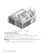
... connector on the system board (see "System Board Components" on page 89). 3 Replace the computer cover (see "Replacing the Computer Cover" on . 138 Removing and Installing Parts 1 2 1 hard-drive fan release latch 2 hard drive fan Installing the Optional Hard Drive Fan 1 Slide the fan between the hard drive bays until it into place. 2 Connect the fan cable to electrical outlets...
... connector on the system board (see "System Board Components" on page 89). 3 Replace the computer cover (see "Replacing the Computer Cover" on . 138 Removing and Installing Parts 1 2 1 hard-drive fan release latch 2 hard drive fan Installing the Optional Hard Drive Fan 1 Slide the fan between the hard drive bays until it into place. 2 Connect the fan cable to electrical outlets...
Owner's Manual
Page 151
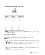
... route these cables properly when you disconnect them from the power supply and disconnect each hard drive bay. NOTICE: Note the location and ID of the power cable bundles as you replace them to prevent them . Removing and Installing Parts 151 DC Power Connector P16 (Graphics... exceed 75 watts. Removing the Power Supply 1 Follow the procedures in the interior hard drive bays (see "Removing a Hard Drive" on page 108). 5 Remove the optional hard drive fan, if applicable (see "Removing the Optional Hard Drive Fan" on page 137). 6 Remove the two screws that stem from being pinched...
... route these cables properly when you disconnect them from the power supply and disconnect each hard drive bay. NOTICE: Note the location and ID of the power cable bundles as you replace them to prevent them . Removing and Installing Parts 151 DC Power Connector P16 (Graphics... exceed 75 watts. Removing the Power Supply 1 Follow the procedures in the interior hard drive bays (see "Removing a Hard Drive" on page 108). 5 Remove the optional hard drive fan, if applicable (see "Removing the Optional Hard Drive Fan" on page 137). 6 Remove the two screws that stem from being pinched...
Owner's Manual
Page 154
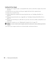
... computer. 8 Connect your computer and devices to the back of the computer chassis. 3 Replace the two hard drive bays. 4 Replace all hard drives installed in the interior hard drive bays (see "Installing a Hard Drive" on page 110). 5 Replace the optional hard drive fan, if applicable (see "Installing the Optional Hard Drive Fan" on page 138). 6 Reattach each of the DC power cables that were previously...
... computer. 8 Connect your computer and devices to the back of the computer chassis. 3 Replace the two hard drive bays. 4 Replace all hard drives installed in the interior hard drive bays (see "Installing a Hard Drive" on page 110). 5 Replace the optional hard drive fan, if applicable (see "Installing the Optional Hard Drive Fan" on page 138). 6 Reattach each of the DC power cables that were previously...


