Owner's Manual
Page 7
...DVD Drive 116 Liquid Cooling Assembly 119 Removing the Liquid Cooling Assembly 119 Installing the Liquid Cooling Assembly 121 Processor 122 Removing the Processor 122 Installing the Processor 123 Battery 125 Replacing the Battery 125 Removing the Computer Stand 126 Replacing the Computer Cover 127 6 ... Computer 143 Computer, Keyboard, and Monitor 143 Mouse 144 Floppy Drive 144 CDs and DVDs 144 Dell Hardware Warranty Support Policy (U.S. Only 145 Definition of "Dell-Installed" Software and Peripherals 145 Definition of "Third-Party" Software and Peripherals 145 Contents 7
...DVD Drive 116 Liquid Cooling Assembly 119 Removing the Liquid Cooling Assembly 119 Installing the Liquid Cooling Assembly 121 Processor 122 Removing the Processor 122 Installing the Processor 123 Battery 125 Replacing the Battery 125 Removing the Computer Stand 126 Replacing the Computer Cover 127 6 ... Computer 143 Computer, Keyboard, and Monitor 143 Mouse 144 Floppy Drive 144 CDs and DVDs 144 Dell Hardware Warranty Support Policy (U.S. Only 145 Definition of "Dell-Installed" Software and Peripherals 145 Definition of "Third-Party" Software and Peripherals 145 Contents 7

Owner's Manual
Page 11
...system on your configuration, providing critical 1 Go to work with other Dell customers • Upgrades - depending on your selections. • How to use Windows XP • How to support.dell.com, select your business segment, and then enter your problem. 4 ...Upgrade information for correct operation of your computer and operating system and installs the updates appropriate for the keyword Desktop System Software. processors, optical drives, and USB devices. Contact information, service call status, support history, service contract, and online discussions with ...
...system on your configuration, providing critical 1 Go to work with other Dell customers • Upgrades - depending on your selections. • How to use Windows XP • How to support.dell.com, select your business segment, and then enter your problem. 4 ...Upgrade information for correct operation of your computer and operating system and installs the updates appropriate for the keyword Desktop System Software. processors, optical drives, and USB devices. Contact information, service call status, support history, service contract, and online discussions with ...
Owner's Manual
Page 43
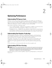
...computer. In dual graphics card configurations, multiple GPUs dynamically share their workload to adjust the operating frequency, or clock speed, of the processor. For a given application, the software selects the optimum rendering (processing) mode. Optimizing Performance 43 Some benefits of data, and may...PCI cards. Benefits of this manner may reduce the operational life of the AGP graphics card slot. Understanding CPU Over-Clocking NOTICE: Dell does not recommend operating the CPU at a time. • Prioritization of the 3-D graphics used in one GPU (graphics processing ...
...computer. In dual graphics card configurations, multiple GPUs dynamically share their workload to adjust the operating frequency, or clock speed, of the processor. For a given application, the software selects the optimum rendering (processing) mode. Optimizing Performance 43 Some benefits of data, and may...PCI cards. Benefits of this manner may reduce the operational life of the AGP graphics card slot. Understanding CPU Over-Clocking NOTICE: Dell does not recommend operating the CPU at a time. • Prioritization of the 3-D graphics used in one GPU (graphics processing ...

Owner's Manual
Page 44
You can make limited adjustments to a frequency that your computer shuts down unexpectedly or is faster than the processor manufacturer's design specifications, and possibly enhance the overall performance of your system. Dell does not guarantee that is unstable, select a lower operating frequency for the CPU. If your computer will ..., 2006 4:02 PM Altering the CPU operating frequency (commonly referred to as over-clocking) enables you to increases the speed of the processor to the CPU operating frequency in system setup (see "System Setup" on page 134). 44 Optimizing Performance
You can make limited adjustments to a frequency that your computer shuts down unexpectedly or is faster than the processor manufacturer's design specifications, and possibly enhance the overall performance of your system. Dell does not guarantee that is unstable, select a lower operating frequency for the CPU. If your computer will ..., 2006 4:02 PM Altering the CPU operating frequency (commonly referred to as over-clocking) enables you to increases the speed of the processor to the CPU operating frequency in system setup (see "System Setup" on page 134). 44 Optimizing Performance
Owner's Manual
Page 55
.... E L I M I N A T E I O N - ENSURE THAT THE PRINTER IS TURNED ON CHECK THE PRINTER CABLE CONNECTIONS - • See the printer documentation for cable connection information. • Ensure that the processor power cable is securely connected to LPT1 (Printer Port). VERIFY THAT THE PRINTER IS RECOGNIZED BY WINDOWS - 1 Click Start, click Control Panel, and then click...
.... E L I M I N A T E I O N - ENSURE THAT THE PRINTER IS TURNED ON CHECK THE PRINTER CABLE CONNECTIONS - • See the printer documentation for cable connection information. • Ensure that the processor power cable is securely connected to LPT1 (Printer Port). VERIFY THAT THE PRINTER IS RECOGNIZED BY WINDOWS - 1 Click Start, click Control Panel, and then click...

Owner's Manual
Page 61
.... To help to install additional memory modules (one module (see "Front View" on page 147). A possible processor failure has occurred. • Reseat the processor (see "Processor" on page 122). • If the problem persists, contact Dell (see "Contacting Dell" on page 147). Advanced Troubleshooting 61 book.book Page 61 Friday, October 27, 2006 4:02 PM...
.... To help to install additional memory modules (one module (see "Front View" on page 147). A possible processor failure has occurred. • Reseat the processor (see "Processor" on page 122). • If the problem persists, contact Dell (see "Contacting Dell" on page 147). Advanced Troubleshooting 61 book.book Page 61 Friday, October 27, 2006 4:02 PM...
Owner's Manual
Page 80
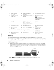
...) 21 password jumper (PASSWORD) 22 power connector (POWER2) 23 floppy drive (DSKT) 24 card cage fan connector (FAN_CAGE) 25 liquid cooling assembly (TEC_PUMP) 26 processor (CPU) 27 processor fan connector (FAN1_CPU) Memory You can increase your computer memory by your computer, see "Memory" on the system board. 80 Removing and Installing Parts...
...) 21 password jumper (PASSWORD) 22 power connector (POWER2) 23 floppy drive (DSKT) 24 card cage fan connector (FAN_CAGE) 25 liquid cooling assembly (TEC_PUMP) 26 processor (CPU) 27 processor fan connector (FAN1_CPU) Memory You can increase your computer memory by your computer, see "Memory" on the system board. 80 Removing and Installing Parts...

Owner's Manual
Page 81
... installed. • Be sure to install a single memory module in DIMM connector 1, the connector closest to the processor, before you purchased the new modules from Dell. Otherwise, your original memory modules in pairs either in any new modules that you may not start properly. NOTE:... 4 (black securing clips) NOTICE: If you remove your original memory modules from the computer during a memory upgrade, keep them separate from Dell is covered under your computer warranty. Removing and Installing Parts 81 If possible, do not pair an original memory module with a new memory ...
... installed. • Be sure to install a single memory module in DIMM connector 1, the connector closest to the processor, before you purchased the new modules from Dell. Otherwise, your original memory modules in pairs either in any new modules that you may not start properly. NOTE:... 4 (black securing clips) NOTICE: If you remove your original memory modules from the computer during a memory upgrade, keep them separate from Dell is covered under your computer warranty. Removing and Installing Parts 81 If possible, do not pair an original memory module with a new memory ...

Owner's Manual
Page 82
Installing Memory CAUTION: Before you are using a wrist grounding strap or by using a 32-bit operating system such as Microsoft® Windows® XP, your computer will support a maximum of 4 GB of memory. NOTICE: To avoid electrostatic discharge and damage to internal components, ground yourself by periodically touching an ... operating system, your computer will support a maximum of 8 GB (2-GB DIMMs in each end of the memory module connector. 1 2 1 memory connector closest to 2 securing clips (2) processor 3 3 memory connector 82 Removing and Installing Parts
Installing Memory CAUTION: Before you are using a wrist grounding strap or by using a 32-bit operating system such as Microsoft® Windows® XP, your computer will support a maximum of 4 GB of memory. NOTICE: To avoid electrostatic discharge and damage to internal components, ground yourself by periodically touching an ... operating system, your computer will support a maximum of 8 GB (2-GB DIMMs in each end of the memory module connector. 1 2 1 memory connector closest to 2 securing clips (2) processor 3 3 memory connector 82 Removing and Installing Parts
Owner's Manual
Page 119
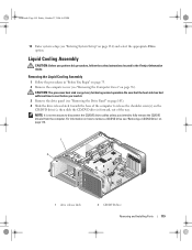
... Liquid Cooling Assembly 1 Follow the procedures in the Product Information Guide. For information on how to release the shoulder screw(s) on page 76). CAUTION: The processor heat sink can get very hot during normal operation. Be sure that the heat sink has had sufficient time to cool before you intend to...
... Liquid Cooling Assembly 1 Follow the procedures in the Product Information Guide. For information on how to release the shoulder screw(s) on page 76). CAUTION: The processor heat sink can get very hot during normal operation. Be sure that the heat sink has had sufficient time to cool before you intend to...
Owner's Manual
Page 120
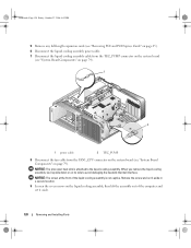
NOTICE: The processor heat sink is not captive. Remove the screw and set it aside in a secure location. 9 Loosen the seven screws on the liquid cooling assembly, then ...
NOTICE: The processor heat sink is not captive. Remove the screw and set it aside in a secure location. 9 Loosen the seven screws on the liquid cooling assembly, then ...
Owner's Manual
Page 121
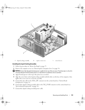
.... 3 Apply thermal grease to the top of the processor, as needed. 4 Align the screw holes on the liquid cooling assembly with the holes on the base of the computer, then tighten the seven screws ... the FAN1_CPU connector on the system board (see "System Board Components" on page 79). 6 Connect the liquid cooling assembly cable to the top of the processor. Removing and Installing Parts 121 NOTICE: Ensure that adequate thermal grease is a requirement for ensuring adequate thermal bonding, which is applied to the TEC_PUMP connector...
.... 3 Apply thermal grease to the top of the processor, as needed. 4 Align the screw holes on the liquid cooling assembly with the holes on the base of the computer, then tighten the seven screws ... the FAN1_CPU connector on the system board (see "System Board Components" on page 79). 6 Connect the liquid cooling assembly cable to the top of the processor. Removing and Installing Parts 121 NOTICE: Ensure that adequate thermal grease is a requirement for ensuring adequate thermal bonding, which is applied to the TEC_PUMP connector...
Owner's Manual
Page 122
... October 27, 2006 4:02 PM 8 Gently slide the CD/DVD drive(s) into the computer. 12 Connect your system board. Removing the Processor 1 Follow the procedures in the Product Information Guide. Performing these steps incorrectly could damage your computer and devices to electrical outlets, and turn...87). 11 Close the computer cover (see "Replacing the Computer Cover" on the system board. 4 Remove the liquid cooling assembly (see "Dell Hardware Warranty Support Policy (U.S. Only)" on page 106). 10 Replace any of the procedures in this section, follow the safety instructions in "Before...
... October 27, 2006 4:02 PM 8 Gently slide the CD/DVD drive(s) into the computer. 12 Connect your system board. Removing the Processor 1 Follow the procedures in the Product Information Guide. Performing these steps incorrectly could damage your computer and devices to electrical outlets, and turn...87). 11 Close the computer cover (see "Replacing the Computer Cover" on the system board. 4 Remove the liquid cooling assembly (see "Dell Hardware Warranty Support Policy (U.S. Only)" on page 106). 10 Replace any of the procedures in this section, follow the safety instructions in "Before...

Owner's Manual
Page 123
.... book.book Page 123 Friday, October 27, 2006 4:02 PM 6 Lift the socket release lever and open the processor cover. 1 2 3 4 1 processor cover 4 socket release lever 2 processor 3 socket 7 Remove the processor from the socket. Leave the release lever extended in the socket to avoid permanent damage to the... processor and the computer when you turn on the computer. 2 If the release lever on the back of the computer. 1 Unpack the new processor. Removing and Installing Parts 123 Installing the Processor NOTICE: Ground yourself by touching an ...
.... book.book Page 123 Friday, October 27, 2006 4:02 PM 6 Lift the socket release lever and open the processor cover. 1 2 3 4 1 processor cover 4 socket release lever 2 processor 3 socket 7 Remove the processor from the socket. Leave the release lever extended in the socket to avoid permanent damage to the... processor and the computer when you turn on the computer. 2 If the release lever on the back of the computer. 1 Unpack the new processor. Removing and Installing Parts 123 Installing the Processor NOTICE: Ground yourself by touching an ...

Owner's Manual
Page 124
...124 Removing and Installing Parts Be careful not to touch or bend the pins on the system board. 4 Set the processor lightly in the socket, close the processor cover. 6 Pivot the socket release lever back toward the socket and snap it into place to electrical outlets, and..." on page 121). 9 Reconnect the power cables to the top of the processor and socket. 1 2 3 5 4 1 processor cover 4 socket release lever 2 processor 5 socket pin-1 indicator 3 socket NOTICE: Socket pins are delicate. When the processor is positioned correctly, press it with the socket, and do not use excessive ...
...124 Removing and Installing Parts Be careful not to touch or bend the pins on the system board. 4 Set the processor lightly in the socket, close the processor cover. 6 Pivot the socket release lever back toward the socket and snap it into place to electrical outlets, and..." on page 121). 9 Reconnect the power cables to the top of the processor and socket. 1 2 3 5 4 1 processor cover 4 socket release lever 2 processor 5 socket pin-1 indicator 3 socket NOTICE: Socket pins are delicate. When the processor is positioned correctly, press it with the socket, and do not use excessive ...

Owner's Manual
Page 129
... 1066-MHz data rate PCI Express Appendix 129 book.book Page 129 Friday, October 27, 2006 4:02 PM Appendix Specifications Processor Processor type Cache Memory Type Memory connectors Memory capacities Minimum memory Maximum memory BIOS address Computer Information Chipset Northbridge Southbridge DMA channels Interrupt... levels BIOS chip (NVRAM) NIC System clock Video Type Intel® Core™ 2 Duo (dual-core processor) Intel® Core™ 2 Extreme (quad-core processor) at least 1 MB 533-, and 667-MHz DDR2 unbuffered SDRAM four 512 MB, 1 GB, or 2 GB non-ECC...
... 1066-MHz data rate PCI Express Appendix 129 book.book Page 129 Friday, October 27, 2006 4:02 PM Appendix Specifications Processor Processor type Cache Memory Type Memory connectors Memory capacities Minimum memory Maximum memory BIOS address Computer Information Chipset Northbridge Southbridge DMA channels Interrupt... levels BIOS chip (NVRAM) NIC System clock Video Type Intel® Core™ 2 Duo (dual-core processor) Intel® Core™ 2 Extreme (quad-core processor) at least 1 MB 533-, and 667-MHz DDR2 unbuffered SDRAM four 512 MB, 1 GB, or 2 GB non-ECC...

Owner's Manual
Page 135
... each option listed in the Options List. Scroll up and down -arrow keys. Identifies the processor type, clock speed, bus speed, L2 cache, ID, and whether the processor is highlighted, the Options Field displays more information about your computer and make that option and ... 64-bit technology. and right-arrow keys to your computer, including installed hardware, power conservation, and security features. System System Info Processor Info Memory Info PCI Info Date/Time Lists system information, such as listed. System Setup Options NOTE: Depending on the left - ...
... each option listed in the Options List. Scroll up and down -arrow keys. Identifies the processor type, clock speed, bus speed, L2 cache, ID, and whether the processor is highlighted, the Options Field displays more information about your computer and make that option and ... 64-bit technology. and right-arrow keys to your computer, including installed hardware, power conservation, and security features. System System Info Processor Info Memory Info PCI Info Date/Time Lists system information, such as listed. System Setup Options NOTE: Depending on the left - ...

Owner's Manual
Page 137
... are in use the port is enabled. The port is configured at 3E8h with USB support will not recognize USB storage devices. Specifies whether the processor has more than that the CPU operates at 3F8h with an additional core enabled. Enables or disables the internal USB controller. • Off - The 1394a...
... are in use the port is enabled. The port is configured at 3E8h with USB support will not recognize USB storage devices. Specifies whether the processor has more than that the CPU operates at 3F8h with an additional core enabled. Enables or disables the internal USB controller. • Off - The 1394a...

Owner's Manual
Page 170
...main memory or an independent high-speed storage device. The standard unit for audio and software programs. CD drive - A communication pathway between the processor and devices. bus speed - byte - C C - Secondary cache which can either a reserved section of DDR SDRAM that uses optical technology to... referred to as a disk drive, printer, or keyboard that can transfer information. The cache enhances the efficiency of data between the processor and memory or between the components in your computer. CRIMM - CD player - A Windows utility that indicates how fast a bus can...
...main memory or an independent high-speed storage device. The standard unit for audio and software programs. CD drive - A communication pathway between the processor and devices. bus speed - byte - C C - Secondary cache which can either a reserved section of DDR SDRAM that uses optical technology to... referred to as a disk drive, printer, or keyboard that can transfer information. The cache enhances the efficiency of data between the processor and memory or between the components in your computer. CRIMM - CD player - A Windows utility that indicates how fast a bus can...

Owner's Manual
Page 171
... most CD media and write to use to read data from disk storage. E ECC - DIN connector - Memory that allows the operating system to bypass the processor. Software that stores information in computer and communications equipment. The DVD player displays a window with common rules and procedures for digital transmission between RAM and...
... most CD media and write to use to read data from disk storage. E ECC - DIN connector - Memory that allows the operating system to bypass the processor. Software that stores information in computer and communications equipment. The DVD player displays a window with common rules and procedures for digital transmission between RAM and...


