
Owner's Manual
Page 4
5 Removing and Installing Parts 75 Before You Begin 75 Recommended Tools 75 Preparing to Work Inside Your Computer 75 Removing the Computer Cover 76 Inside View of Your Computer ...
5 Removing and Installing Parts 75 Before You Begin 75 Recommended Tools 75 Preparing to Work Inside Your Computer 75 Removing the Computer Cover 76 Inside View of Your Computer ...

Owner's Manual
Page 43
...safety instructions in the Product Information Guide. If the battery still does not work , ensure that the part is correctly installed. • If a peripheral device does not work properly, contact Dell (see the program's documentation. If the floppy, CD, or DVD drive is incorrectly installed. If... same or equivalent type recommended by the manufacturer. Replace the battery only with your computer: • If you added or removed a part before the problem started, review the installation procedures and ensure that the device is properly connected. • If an error message appears ...
...safety instructions in the Product Information Guide. If the battery still does not work , ensure that the part is correctly installed. • If a peripheral device does not work properly, contact Dell (see the program's documentation. If the floppy, CD, or DVD drive is incorrectly installed. If... same or equivalent type recommended by the manufacturer. Replace the battery only with your computer: • If you added or removed a part before the problem started, review the installation procedures and ensure that the device is properly connected. • If an error message appears ...
Owner's Manual
Page 63
... any error codes and problem descriptions exactly as they appear and follow the instructions on the keyboard to exit the Dell Diagnostics and restart the computer. NOTE: Write down your part. To avoid possible keyboard failure, press and release in system setup. 7 At the CD-ROM Startup Menu, ...use the up - If you wait too long and the Windows logo appears, continue to wait until you see "Dell Diagnostics Main Menu" on the keyboard...
... any error codes and problem descriptions exactly as they appear and follow the instructions on the keyboard to exit the Dell Diagnostics and restart the computer. NOTE: Write down your part. To avoid possible keyboard failure, press and release in system setup. 7 At the CD-ROM Startup Menu, ...use the up - If you wait too long and the Windows logo appears, continue to wait until you see "Dell Diagnostics Main Menu" on the keyboard...

Owner's Manual
Page 73
...outlet, power strip, or convenience receptacle. Instead, hold a card by its edges or by its metal mounting bracket. Removing and Installing Parts 75 CAUTION: Before you begin any of the branch circuit rating. Seek assistance before attempting to lift, move, or tilt the computer and... of the following tools: • Small flat-blade screwdriver • Phillips screwdriver • Flash BIOS update (see the Dell support website at support.dell.com) Preparing to Work Inside Your Computer Use the following safety guidelines to help protect your computer from potential damage and to...
...outlet, power strip, or convenience receptacle. Instead, hold a card by its edges or by its metal mounting bracket. Removing and Installing Parts 75 CAUTION: Before you begin any of the branch circuit rating. Seek assistance before attempting to lift, move, or tilt the computer and... of the following tools: • Small flat-blade screwdriver • Phillips screwdriver • Flash BIOS update (see the Dell support website at support.dell.com) Preparing to Work Inside Your Computer Use the following safety guidelines to help protect your computer from potential damage and to...

Owner's Manual
Page 74
... help of an assistant, carefully lay the computer down on the cable itself. The computer performs a shutdown of desk top space. 76 Removing and Installing Parts NOTE: Ensure that the work in the Product Information Guide. Removing the Computer Cover CAUTION: Before you cannot shut down the computer using a wrist grounding...
... help of an assistant, carefully lay the computer down on the cable itself. The computer performs a shutdown of desk top space. 76 Removing and Installing Parts NOTE: Ensure that the work in the Product Information Guide. Removing the Computer Cover CAUTION: Before you cannot shut down the computer using a wrist grounding...

Owner's Manual
Page 75
Removing and Installing Parts 77 1 2 3 4 1 computer cover 4 stabilizing feet (closed) 2 cover release latch 3 cover hinge tabs 3 With the cover release latch pulled back, grip the sides of the cover, then pivot the top of the cover up and away from the computer. 4 Slide the cover forward and up to remove it from the hinge slots, then set it aside in a secure and protected location.
Removing and Installing Parts 77 1 2 3 4 1 computer cover 4 stabilizing feet (closed) 2 cover release latch 3 cover hinge tabs 3 With the cover release latch pulled back, grip the sides of the cover, then pivot the top of the cover up and away from the computer. 4 Slide the cover forward and up to remove it from the hinge slots, then set it aside in a secure and protected location.

Owner's Manual
Page 76
Inside View of Your Computer 2 3 1 5 4 1 CD/DVD drive bays (4) 4 card fan 2 floppy drive/media card reader 5 front fan 3 hard drive bays (4) 78 Removing and Installing Parts
Inside View of Your Computer 2 3 1 5 4 1 CD/DVD drive bays (4) 4 card fan 2 floppy drive/media card reader 5 front fan 3 hard drive bays (4) 78 Removing and Installing Parts

Owner's Manual
Page 77
System Board Components 1 2 3 4 27 26 25 24 23 22 21 20 19 5 6 7 8 9 10 11 12 13 14 15 16 17 18 Removing and Installing Parts 79
System Board Components 1 2 3 4 27 26 25 24 23 22 21 20 19 5 6 7 8 9 10 11 12 13 14 15 16 17 18 Removing and Installing Parts 79

Owner's Manual
Page 78
... connector (FAN2_CPU) NOTICE: The FAN2_CPU connector is not currently used on this system and is not available in the dualgraphics configuration 80 Removing and Installing Parts Do not attach the primary CPU fan to the FAN2_CPU connector. 12 PCI-Express x1 card slot (SLOT1) NOTE: This slot is not available in...
... connector (FAN2_CPU) NOTICE: The FAN2_CPU connector is not currently used on this system and is not available in the dualgraphics configuration 80 Removing and Installing Parts Do not attach the primary CPU fan to the FAN2_CPU connector. 12 PCI-Express x1 card slot (SLOT1) NOTE: This slot is not available in...

Owner's Manual
Page 79
... modules. • If you install modules in performance. NOTE: Always install DDR2 memory modules in pairs of matched memory size and speed. Removing and Installing Parts 81 A pair of matched memory modules installed in DIMM connectors 1 and 2 and another matched pair installed in DIMM connectors 1 and 2 or - Your computer supports DDR2...
... modules. • If you install modules in performance. NOTE: Always install DDR2 memory modules in pairs of matched memory size and speed. Removing and Installing Parts 81 A pair of matched memory modules installed in DIMM connectors 1 and 2 and another matched pair installed in DIMM connectors 1 and 2 or - Your computer supports DDR2...

Owner's Manual
Page 80
...black securing clips) NOTICE: If you remove your computer will support a maximum of 2 GB of the memory module connector. 82 Removing and Installing Parts NOTE: Memory purchased from Dell. If you are using a wrist grounding strap or by using a 64-bit operating system, your original memory modules from the computer during a... module with a new memory module. Addressing Memory Configurations If you are using a 32-bit operating system such as Microsoft® Windows® XP, your computer may have, even if you begin any of memory modules in the Product Information Guide.
...black securing clips) NOTICE: If you remove your computer will support a maximum of 2 GB of the memory module connector. 82 Removing and Installing Parts NOTE: Memory purchased from Dell. If you are using a wrist grounding strap or by using a 64-bit operating system, your original memory modules from the computer during a... module with a new memory module. Addressing Memory Configurations If you are using a 32-bit operating system such as Microsoft® Windows® XP, your computer may have, even if you begin any of memory modules in the Product Information Guide.

Owner's Manual
Page 81
... clips snap into position. 1 2 3 1 memory connector closest to 2 securing clips (2) processor 3 memory connector 4 Align the notch on the bottom of the module. Removing and Installing Parts 83
... clips snap into position. 1 2 3 1 memory connector closest to 2 securing clips (2) processor 3 memory connector 4 Align the notch on the bottom of the module. Removing and Installing Parts 83

Owner's Manual
Page 82
... stating that the memory is difficult to remove, gently ease the module back and forth to remove it from the connector. 84 Removing and Installing Parts If the module is installed correctly, check the amount of the memory module connector. 3 Grasp the module and pull up. NOTICE: To avoid electrostatic discharge...
... stating that the memory is difficult to remove, gently ease the module back and forth to remove it from the connector. 84 Removing and Installing Parts If the module is installed correctly, check the amount of the memory module connector. 3 Grasp the module and pull up. NOTICE: To avoid electrostatic discharge...

Owner's Manual
Page 83
... Express x1 card slot NOTE: If a graphics card is installed in each of the PCI Express x16 card slots in the Product Information Guide. Your Dell™ computer provides the following slots for use. 1 2 4 6 3 5 1 PCI card 4 PCI Express x8 card 7 PCI Express x1 card slot 2 PCI Express x16 card 5 PCI Express...
... Express x1 card slot NOTE: If a graphics card is installed in each of the PCI Express x16 card slots in the Product Information Guide. Your Dell™ computer provides the following slots for use. 1 2 4 6 3 5 1 PCI card 4 PCI Express x8 card 7 PCI Express x1 card slot 2 PCI Express x16 card 5 PCI Express...

Owner's Manual
Page 84
NOTICE: If you remove the card, store it to gain full access to the card. 1 2 3 1 release tab 4 fan bracket 4 2 card retainer 86 Removing and Installing Parts 3 alignment guide Removing PCI and PCI Express Cards NOTICE: To avoid electrostatic discharge and damage to internal components, ground yourself by using a wrist grounding strap ...
NOTICE: If you remove the card, store it to gain full access to the card. 1 2 3 1 release tab 4 fan bracket 4 2 card retainer 86 Removing and Installing Parts 3 alignment guide Removing PCI and PCI Express Cards NOTICE: To avoid electrostatic discharge and damage to internal components, ground yourself by using a wrist grounding strap ...

Owner's Manual
Page 85
.... NOTICE: To connect a network cable, first plug the cable into the network port or device and then plug the cable into place. Removing and Installing Parts 87 6 Press the release tab (if present) on the system board connector as you removed a sound card or a network adapter, see "Network Adapter and Sound...
.... NOTICE: To connect a network cable, first plug the cable into the network port or device and then plug the cable into place. Removing and Installing Parts 87 6 Press the release tab (if present) on the system board connector as you removed a sound card or a network adapter, see "Network Adapter and Sound...

Owner's Manual
Page 86
... at the appropriate card slot and pivot the card retainer back through the chassis wall. 1 2 3 1 release tab 4 fan bracket 4 2 card retainer 88 Removing and Installing Parts 3 alignment guide however, the card is not necessary when installing additional graphics cards; NOTICE: If you remove the card, store it in "Before You Begin...
... at the appropriate card slot and pivot the card retainer back through the chassis wall. 1 2 3 1 release tab 4 fan bracket 4 2 card retainer 88 Removing and Installing Parts 3 alignment guide however, the card is not necessary when installing additional graphics cards; NOTICE: If you remove the card, store it in "Before You Begin...

Owner's Manual
Page 87
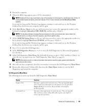
...: Ensure that you may damage the system board. 8 Gently pull the securing tab (if present) and place the card in the slot. Removing and Installing Parts 89 5 Remove the filler bracket or existing card (see "Removing PCI and PCI Express Cards" on page 86) to seat the card. If the card...
...: Ensure that you may damage the system board. 8 Gently pull the securing tab (if present) and place the card in the slot. Removing and Installing Parts 89 5 Remove the filler bracket or existing card (see "Removing PCI and PCI Express Cards" on page 86) to seat the card. If the card...

Owner's Manual
Page 88
... place. 11 If present, lower the card retention device that should be attached to electrical outlets, and then turn them on. 90 Removing and Installing Parts See the documentation for the card for information about the card's cable connections. NOTICE: Before rotating the card retainer back into place, ensure that the...
... place. 11 If present, lower the card retention device that should be attached to electrical outlets, and then turn them on. 90 Removing and Installing Parts See the documentation for the card for information about the card's cable connections. NOTICE: Before rotating the card retainer back into place, ensure that the...

Owner's Manual
Page 89
... card bridge (if present) with your other hand by pulling it aside. 1 2 3 1 graphics card bridge 2 power connectors (2) 3 dual-PCI Express graphics cards Removing and Installing Parts 91 13 Install any other type of PCI or PCI Express cards, see "Removing PCI and PCI Express Cards" on page 86. 1 Follow the procedures...
... card bridge (if present) with your other hand by pulling it aside. 1 2 3 1 graphics card bridge 2 power connectors (2) 3 dual-PCI Express graphics cards Removing and Installing Parts 91 13 Install any other type of PCI or PCI Express cards, see "Removing PCI and PCI Express Cards" on page 86. 1 Follow the procedures...

