
Owner's Manual
Page 3
... solid blue screen appears 51 Other software problems 52 Memory Problems 52 Mouse Problems 53 Network Problems 53 Power Problems...to read 58 3-D image quality is poor 59 4 Advanced Troubleshooting 61 Diagnostic Lights 61 Dell Diagnostics 64 When to Use the Dell Diagnostics 64 Drivers 67 What Is a Driver 67 Identifying Drivers 67 Reinstalling Drivers 67 Using... Microsoft® Windows® XP System Restore 69 Creating a Restore Point 69 Restoring the ...
... solid blue screen appears 51 Other software problems 52 Memory Problems 52 Mouse Problems 53 Network Problems 53 Power Problems...to read 58 3-D image quality is poor 59 4 Advanced Troubleshooting 61 Diagnostic Lights 61 Dell Diagnostics 64 When to Use the Dell Diagnostics 64 Drivers 67 What Is a Driver 67 Identifying Drivers 67 Reinstalling Drivers 67 Using... Microsoft® Windows® XP System Restore 69 Creating a Restore Point 69 Restoring the ...

Owner's Manual
Page 4
... Work Inside Your Computer 75 Removing the Computer Cover 76 Inside View of Your Computer 78 System Board Components 79 Memory 81 DDR2 Memory Overview 81 Addressing Memory Configurations 82 Installing Memory 82 Removing Memory 84 Cards 85 Removing PCI and PCI Express Cards 86 Installing PCI and PCI Express Cards 88 Removing a PCI Express...
... Work Inside Your Computer 75 Removing the Computer Cover 76 Inside View of Your Computer 78 System Board Components 79 Memory 81 DDR2 Memory Overview 81 Addressing Memory Configurations 82 Installing Memory 82 Removing Memory 84 Cards 85 Removing PCI and PCI Express Cards 86 Installing PCI and PCI Express Cards 88 Removing a PCI Express...

Owner's Manual
Page 9
..., and online discussions with support • Reference - DSS automatically detects your selections. • How to use Windows XP • How to work with other Dell customers • Upgrades - depending on the screen. Service call and order status, and warranty and repair information •...my computer configuration, product specifications, and white papers • Downloads - DSS is NOTE: The support.dell.com user interface may vary necessary for components, such as the memory, hard drive, and operating system • Customer Care - Find It Here • Solutions - ...
..., and online discussions with support • Reference - DSS automatically detects your selections. • How to use Windows XP • How to work with other Dell customers • Upgrades - depending on the screen. Service call and order status, and warranty and repair information •...my computer configuration, product specifications, and white papers • Downloads - DSS is NOTE: The support.dell.com user interface may vary necessary for components, such as the memory, hard drive, and operating system • Customer Care - Find It Here • Solutions - ...
Owner's Manual
Page 13
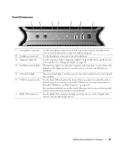
... that typically remain connected, such as printers and keyboards. 7 IEEE 1394 connector Use the IEEE 1394 connector for high-speed data devices such as flash memory keys, cameras, or bootable USB devices. The light may also be on when a device such as your computer (see "Boot Sequence" on when a good connection...
... that typically remain connected, such as printers and keyboards. 7 IEEE 1394 connector Use the IEEE 1394 connector for high-speed data devices such as flash memory keys, cameras, or bootable USB devices. The light may also be on when a device such as your computer (see "Boot Sequence" on when a good connection...

Owner's Manual
Page 16
... such as a handheld device, to maneuver. On computers with a sound card, use the front USB connectors for devices that typically remain connected, such as flash memory keys, cameras, or bootable USB devices. Seek assistance before attempting to lift, move, or tilt the computer and always lift correctly to attach multichannel-capable...
... such as a handheld device, to maneuver. On computers with a sound card, use the front USB connectors for devices that typically remain connected, such as flash memory keys, cameras, or bootable USB devices. Seek assistance before attempting to lift, move, or tilt the computer and always lift correctly to attach multichannel-capable...

Owner's Manual
Page 31
... then click Medium (16 bit). 6 Click OK. Setting Up and Using Your Computer 33 Adjusting the Volume NOTE: When the speakers are using too much memory and preventing DVD playback, adjust the display properties. 1 Click Start, then click Control Panel. 2 Under Pick a category, click Appearance and Themes. 3 Under Pick a task..., click...
... then click Medium (16 bit). 6 Click OK. Setting Up and Using Your Computer 33 Adjusting the Volume NOTE: When the speakers are using too much memory and preventing DVD playback, adjust the display properties. 1 Click Start, then click Control Panel. 2 Under Pick a category, click Appearance and Themes. 3 Under Pick a task..., click...

Owner's Manual
Page 34
...Using Your Computer Using a Media Card Reader (Optional) CAUTION: Before you are familiar with CD recording techniques. The media card reader supports the following memory types: • xD-Picture card • SmartMedia card (SMC) • CompactFlash card Type I and II (CF I/II) • MicroDrive ...card • SecureDigital card (SD) • MiniSD card • MultiMediaCard (MMC) • Reduced-size MultiMediaCard (RS-MMC) • Memory Stick (MS/MS Pro/MS Duo/MS Pro Duo) For information on installing a media card reader, see "Installing a Media Card Reader" on the CD...
...Using Your Computer Using a Media Card Reader (Optional) CAUTION: Before you are familiar with CD recording techniques. The media card reader supports the following memory types: • xD-Picture card • SmartMedia card (SMC) • CompactFlash card Type I and II (CF I/II) • MicroDrive ...card • SecureDigital card (SD) • MiniSD card • MultiMediaCard (MMC) • Reduced-size MultiMediaCard (RS-MMC) • Memory Stick (MS/MS Pro/MS Duo/MS Pro Duo) For information on installing a media card reader, see "Installing a Media Card Reader" on the CD...

Owner's Manual
Page 35
1 2 4 3 1 xD-Picture card and SmartMedia Card (SMC) 4 CompactFlash card Type I and II (CF I/II) and MicroDrive card 2 Memory Stick (MS/MS 3 Secure Digital card Pro/MS Duo/MS Pro Duo) (SD/miniSD)/MultiMedia- Setting Up and Using Your Computer 37 Card (MMC/RS-MMC) 1 Inspect the media card to determine the proper orientation for proper orientation, and then try again. If you encounter resistance, remove the card, check for insertion. 2 Slide the media card into the appropriate slot of the media card reader until it is completely seated in the connector.
1 2 4 3 1 xD-Picture card and SmartMedia Card (SMC) 4 CompactFlash card Type I and II (CF I/II) and MicroDrive card 2 Memory Stick (MS/MS 3 Secure Digital card Pro/MS Duo/MS Pro Duo) (SD/miniSD)/MultiMedia- Setting Up and Using Your Computer 37 Card (MMC/RS-MMC) 1 Inspect the media card to determine the proper orientation for proper orientation, and then try again. If you encounter resistance, remove the card, check for insertion. 2 Slide the media card into the appropriate slot of the media card reader until it is completely seated in the connector.

Owner's Manual
Page 38
... becomes corrupted, Windows XP recreates the hibernate file automatically. To set standby mode to entering hibernate mode. When the computer exits from standby mode, press a key on the hard drive, and then completely turning off the computer. To immediately activate standby mode without a period of the computer memory, Dell creates an appropriately sized...
... becomes corrupted, Windows XP recreates the hibernate file automatically. To set standby mode to entering hibernate mode. When the computer exits from standby mode, press a key on the hard drive, and then completely turning off the computer. To immediately activate standby mode without a period of the computer memory, Dell creates an appropriately sized...

Owner's Manual
Page 50
... - • Save and close any open programs you are not using is supported by your computer, see "Memory" on page 127. • Run the Dell Diagnostics (see "Dell Diagnostics" on page 64). 52 Solving Problems For more information about the type of the procedures in this section, follow the safety instructions in the...
... - • Save and close any open programs you are not using is supported by your computer, see "Memory" on page 127. • Run the Dell Diagnostics (see "Dell Diagnostics" on page 64). 52 Solving Problems For more information about the type of the procedures in this section, follow the safety instructions in the...

Owner's Manual
Page 53
... cable is securely connected to the system board power connector (POWER2) (see "System Board Components" on page 79). • Remove and then reinstall all memory modules (see "Memory" on page 81). • Remove and then reinstall any of interference are securely connected to the same electrical outlet Printer Problems CAUTION: Before you...
... cable is securely connected to the system board power connector (POWER2) (see "System Board Components" on page 79). • Remove and then reinstall all memory modules (see "Memory" on page 81). • Remove and then reinstall any of interference are securely connected to the same electrical outlet Printer Problems CAUTION: Before you...

Owner's Manual
Page 59
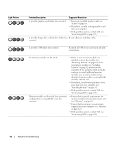
...page 54). • If the problem persists, contact Dell (see "Installing Memory" on page 145). When the computer starts normally, the lights flash before booting to install additional memory modules (one module (see "Contacting Dell" on page 82) and restart the computer. The ...a time) until you begin any of the lights help troubleshoot a problem, your computer (see "Installing Memory" on page 82). • If the problem persists, contact Dell (see "Contacting Dell" on page 13). A possible processor failure has occurred. • Reseat the processor (see "Processor"...
...page 54). • If the problem persists, contact Dell (see "Installing Memory" on page 145). When the computer starts normally, the lights flash before booting to install additional memory modules (one module (see "Contacting Dell" on page 82) and restart the computer. The ...a time) until you begin any of the lights help troubleshoot a problem, your computer (see "Installing Memory" on page 82). • If the problem persists, contact Dell (see "Contacting Dell" on page 13). A possible processor failure has occurred. • Reseat the processor (see "Processor"...
Owner's Manual
Page 60
... failure has occurred. • Reseat any installed graphics cards (see "Cards" on page 85). • If available, install a working memory of the same type into your computer. • If the problem persists, contact Dell (see "Contacting Dell" on page 145). A possible floppy drive or hard drive failure has Reseat all cable connections. No...
... failure has occurred. • Reseat any installed graphics cards (see "Cards" on page 85). • If available, install a working memory of the same type into your computer. • If the problem persists, contact Dell (see "Contacting Dell" on page 145). A possible floppy drive or hard drive failure has Reseat all cable connections. No...

Owner's Manual
Page 64
...information in the device list in the system and can be used to customize the tests you want to run from system setup, memory, and various internal tests, and it appears and follow the instructions on your computer or all devices from the Custom Test or ...Custom Test only) Function Displays the results of the problem you are having. The following tabs provide additional information for tests run . When contacting Dell support, have your computer. Displays error conditions encountered, error codes, and the problem description. Allows you to customize the test, if applicable,...
...information in the device list in the system and can be used to customize the tests you want to run from system setup, memory, and various internal tests, and it appears and follow the instructions on your computer or all devices from the Custom Test or ...Custom Test only) Function Displays the results of the problem you are having. The following tabs provide additional information for tests run . When contacting Dell support, have your computer. Displays error conditions encountered, error codes, and the problem description. Allows you to customize the test, if applicable,...

Owner's Manual
Page 78
... FAN2_CPU connector. 12 PCI-Express x1 card slot (SLOT1) NOTE: This slot is not available in the dualgraphics configuration 80 Removing and Installing Parts 1 white memory module connectors (DIMM_1-2) 15 PCI-Express x16 card slot (SLOT4) support memory modules or memory module risers 2 black memory module connectors (DIMM_3-4) 16 PCI card slot (SLOT5) support...
... FAN2_CPU connector. 12 PCI-Express x1 card slot (SLOT1) NOTE: This slot is not available in the dualgraphics configuration 80 Removing and Installing Parts 1 white memory module connectors (DIMM_1-2) 15 PCI-Express x16 card slot (SLOT4) support memory modules or memory module risers 2 black memory module connectors (DIMM_3-4) 16 PCI card slot (SLOT5) support...

Owner's Manual
Page 79
...the type of matched memory size and speed. NOTE: Always install DDR2 memory modules in pairs of memory supported by your computer memory by installing memory modules on the system board. Memory You can increase your computer, see "Memory" on page 127. DDR2 Memory Overview • DDR2 memory modules should be installed...the order indicated on the upper-right or upper-left corner of the slowest module installed. • Be sure to install a single memory module in DIMM connector 1, the connector closest to the processor, before you install mixed pairs of PC2-4300 (DDR2 533-MHz) and...
...the type of matched memory size and speed. NOTE: Always install DDR2 memory modules in pairs of memory supported by your computer memory by installing memory modules on the system board. Memory You can increase your computer, see "Memory" on page 127. DDR2 Memory Overview • DDR2 memory modules should be installed...the order indicated on the upper-right or upper-left corner of the slowest module installed. • Be sure to install a single memory module in DIMM connector 1, the connector closest to the processor, before you install mixed pairs of PC2-4300 (DDR2 533-MHz) and...

Owner's Manual
Page 80
...bit operating system such as Microsoft® Windows® XP, your original memory modules in pairs either in the Product Information Guide. NOTE: Memory purchased from Dell is covered under your original memory modules from the computer during a memory upgrade, keep them separate from any of 8 GB... NOTICE: If you purchased the new modules from Dell. B A A matched pair of modules in DIMM connectors 1 B matched pair of memory modules in each end of memory. Otherwise, your computer will support a maximum of 2 GB of the memory module connector. 82 Removing and Installing Parts If ...
...bit operating system such as Microsoft® Windows® XP, your original memory modules in pairs either in the Product Information Guide. NOTE: Memory purchased from Dell is covered under your original memory modules from the computer during a memory upgrade, keep them separate from any of 8 GB... NOTICE: If you purchased the new modules from Dell. B A A matched pair of modules in DIMM connectors 1 B matched pair of memory modules in each end of memory. Otherwise, your computer will support a maximum of 2 GB of the memory module connector. 82 Removing and Installing Parts If ...

Owner's Manual
Page 81
... connector while you insert the module correctly, the securing clips snap into the cutouts at each end of the module. Removing and Installing Parts 83 1 2 3 1 memory connector closest to 2 securing clips (2) processor 3 memory connector 4 Align the notch on the bottom of the module with the crossbar in the connector. 3 2 1 4 1 cutouts (2) 4 crossbar...
... connector while you insert the module correctly, the securing clips snap into the cutouts at each end of the module. Removing and Installing Parts 83 1 2 3 1 memory connector closest to 2 securing clips (2) processor 3 memory connector 4 Align the notch on the bottom of the module with the crossbar in the connector. 3 2 1 4 1 cutouts (2) 4 crossbar...

Owner's Manual
Page 82
... to remove, gently ease the module back and forth to electrical outlets, and turn them on. 8 When the message appears stating that the memory is installed correctly, check the amount of the procedures in this section, follow the safety instructions in "Before You Begin" on your Windows desktop... and click Properties. 11 Click the General tab. 12 To verify that memory size has changed, press to continue. 9 Log on to your computer and devices to remove it from the connector. 84 Removing and Installing Parts...
... to remove, gently ease the module back and forth to electrical outlets, and turn them on. 8 When the message appears stating that the memory is installed correctly, check the amount of the procedures in this section, follow the safety instructions in "Before You Begin" on your Windows desktop... and click Properties. 11 Click the General tab. 12 To verify that memory size has changed, press to continue. 9 Log on to your computer and devices to remove it from the connector. 84 Removing and Installing Parts...

Owner's Manual
Page 125
F0000h Nvidia C19/MCP55 five 24 4 Mb integrated network interface capable of memory available to the operating system. Appendix Specifications Processor Processor type Cache Memory Type Memory connectors Memory capacities Minimum memory Maximum memory BIOS address Computer Information Chipset DMA channels Interrupt levels BIOS chip (NVRAM) NIC System clock Video... four 256 MB, 512 MB, 1 GB, or 2 GB non-ECC 512 MB 2 GB or 8 GB NOTE: See "Addressing Memory Configurations" on page 82 to processor) PCI Express Appendix 127 or 1066-MHz data rate (varies according to verify the amount of 10/...
F0000h Nvidia C19/MCP55 five 24 4 Mb integrated network interface capable of memory available to the operating system. Appendix Specifications Processor Processor type Cache Memory Type Memory connectors Memory capacities Minimum memory Maximum memory BIOS address Computer Information Chipset DMA channels Interrupt levels BIOS chip (NVRAM) NIC System clock Video... four 256 MB, 512 MB, 1 GB, or 2 GB non-ECC 512 MB 2 GB or 8 GB NOTE: See "Addressing Memory Configurations" on page 82 to processor) PCI Express Appendix 127 or 1066-MHz data rate (varies according to verify the amount of 10/...


