Owner's Manual
Page 4
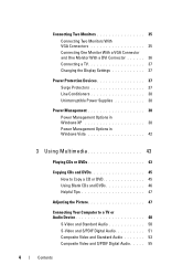
... Connector and One Monitor With a DVI Connector 36 Connecting a TV 37 Changing the Display Settings 37 Power Protection Devices 37 Surge Protectors 37 Line Conditioners 38 Uninterruptible Power Supplies 38 Power Management 38 Power Management Options in Windows XP 38 Power Management Options in Windows Vista 42 3 Using Multimedia 43 Playing CDs or DVDs 43 Copying CDs...
... Connector and One Monitor With a DVI Connector 36 Connecting a TV 37 Changing the Display Settings 37 Power Protection Devices 37 Surge Protectors 37 Line Conditioners 38 Uninterruptible Power Supplies 38 Power Management 38 Power Management Options in Windows XP 38 Power Management Options in Windows Vista 42 3 Using Multimedia 43 Playing CDs or DVDs 43 Copying CDs...
Owner's Manual
Page 20
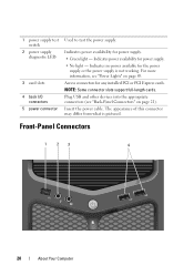
... may differ from what is not working. Indicates power availability for any installed PCI or PCI Express cards. Access connectors for power supply. • No light - Indicates power availability for the power supply or the power supply is pictured. NOTE: Some connector slots support full-length cards. Insert the power cable. 1 power supply test switch 2 power supply diagnostic LED 3 card slots 4 back I/O connectors...
... may differ from what is not working. Indicates power availability for any installed PCI or PCI Express cards. Access connectors for power supply. • No light - Indicates power availability for the power supply or the power supply is pictured. NOTE: Some connector slots support full-length cards. Insert the power cable. 1 power supply test switch 2 power supply diagnostic LED 3 card slots 4 back I/O connectors...
Owner's Manual
Page 37
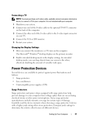
... display settings. A device with surge protection help prevent damage to your computer. Power Protection Devices Several devices are available to protect against power fluctuations and failures: • Surge protectors • Line conditioners • Uninterruptible power supplies (UPS) Surge Protectors Surge protectors and power strips equipped with a higher joule rating offers more protection. Some surge protector...
... display settings. A device with surge protection help prevent damage to your computer. Power Protection Devices Several devices are available to protect against power fluctuations and failures: • Surge protectors • Line conditioners • Uninterruptible power supplies (UPS) Surge Protectors Surge protectors and power strips equipped with a higher joule rating offers more protection. Some surge protector...
Owner's Manual
Page 38
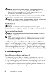
... and you can reduce the amount of power while data is being saved to the hard drive may result in Windows XP The Microsoft Windows XP power management features can use standby mode or hibernate mode to reduce power to the operating state it . When ...offer network adapter protection. When lightning occurs in prior to connected devices when AC power is approved by nearby lightning strikes. UPS devices contain a battery that provides surge protection. Uninterruptible Power Supplies NOTICE: Loss of electricity your computer uses when it is available. The battery ...
... and you can reduce the amount of power while data is being saved to the hard drive may result in Windows XP The Microsoft Windows XP power management features can use standby mode or hibernate mode to reduce power to the operating state it . When ...offer network adapter protection. When lightning occurs in prior to connected devices when AC power is approved by nearby lightning strikes. UPS devices contain a battery that provides surge protection. Uninterruptible Power Supplies NOTICE: Loss of electricity your computer uses when it is available. The battery ...
Owner's Manual
Page 90
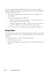
... beeps during start -up . The power supply is not working - The power supply is not receiving power - If your computer. To test the power supply, press the power supply test switch. • If the power supply diagnostic LED is green, power is available for the power supply. • If the power supply diagnostic LED is connected to identify the cause (see "Dell Diagnostics" on page 141). Ensure...
... beeps during start -up . The power supply is not working - The power supply is not receiving power - If your computer. To test the power supply, press the power supply test switch. • If the power supply diagnostic LED is green, power is available for the power supply. • If the power supply diagnostic LED is connected to identify the cause (see "Dell Diagnostics" on page 141). Ensure...
Owner's Manual
Page 116
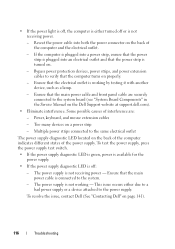
..., contact Dell (See "Contacting Dell" on a power strip - This issue occurs either turned off : - Ensure that the power strip is not receiving power. - To test the power supply, press the power supply test switch. • If the power supply diagnostic LED is green, power is available for the power supply. • If the power supply diagnostic LED is not receiving power - Bypass power protection devices, power strips, and power extension...
..., contact Dell (See "Contacting Dell" on a power strip - This issue occurs either turned off : - Ensure that the power strip is not receiving power. - To test the power supply, press the power supply test switch. • If the power supply diagnostic LED is green, power is available for the power supply. • If the power supply diagnostic LED is not receiving power - Bypass power protection devices, power strips, and power extension...
Owner's Manual
Page 132
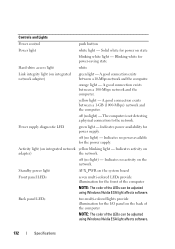
... the network. Indicates no activity on adapter) the network. Standby power light AUX_PWR on state blinking white light - A good connection exists between a 10-Mbps network and the computer. Blinking white for the power supply. A good connection exists between a 100-Mbps network and the... computer. Activity light (on integrated network adapter) green light - Solid white for power on the system board Front panel LEDs seven multi-colored...
... the network. Indicates no activity on adapter) the network. Standby power light AUX_PWR on state blinking white light - A good connection exists between a 10-Mbps network and the computer. Blinking white for the power supply. A good connection exists between a 100-Mbps network and the... computer. Activity light (on integrated network adapter) green light - Solid white for power on the system board Front panel LEDs seven multi-colored...
Owner's Manual
Page 133
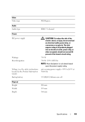
...To reduce the risk of the branch circuit rating. 750 W 750 W: 2559.1 BTU/hr NOTE: Heat dissipation is calculated based upon the power supply rating. auto-sensing power supply-90 V to 265 V at 50/60 Hz 3-V CR2032 lithium coin cell Physical Height Width Depth 488 mm 195 mm 560 mm Specifications 133... The total ampere rating of all products plugged into an electrical outlet, power strip, or other receptacle should not exceed 80 percent of...
...To reduce the risk of the branch circuit rating. 750 W 750 W: 2559.1 BTU/hr NOTE: Heat dissipation is calculated based upon the power supply rating. auto-sensing power supply-90 V to 265 V at 50/60 Hz 3-V CR2032 lithium coin cell Physical Height Width Depth 488 mm 195 mm 560 mm Specifications 133... The total ampere rating of all products plugged into an electrical outlet, power strip, or other receptacle should not exceed 80 percent of...
Owner's Manual
Page 159
... A UPS keeps a computer running for your computer. See resolution. UTP - unshielded twisted pair - Video memory is no electrical power. The amount of video memory installed primarily influences the number of speakers, printer, broadband devices (DSL and cable modems), imaging devices... for a few minutes to enable you or to an unacceptable voltage level. video memory - virus - UPS - uninterruptible power supply - Small UPS systems provide battery power for a low-speed device such as text editors, displays in most telephone networks and some computer networks. video mode ...
... A UPS keeps a computer running for your computer. See resolution. UTP - unshielded twisted pair - Video memory is no electrical power. The amount of video memory installed primarily influences the number of speakers, printer, broadband devices (DSL and cable modems), imaging devices... for a few minutes to enable you or to an unacceptable voltage level. video memory - virus - UPS - uninterruptible power supply - Small UPS systems provide battery power for a low-speed device such as text editors, displays in most telephone networks and some computer networks. video mode ...
Owner's Manual
Page 167
..., 79 screens, 77 T telephone numbers, 141 transferring information to a new computer, 29 troubleshooting conflicts, 95, 121 Dell Diagnostics, 95 Hardware Troubleshooter, 95, 121 restore to previous state, 122 TV connect to devices, 82 V volume adjusting...XP Device Driver Rollback, 118 Files and Settings Transfer Wizard, 29 Hardware Troubleshooter, 95, 121 hibernate mode, 39 PC Restore, 124 reinstalling, 16 standby mode, 39 System Restore, 122 wizards Files and Settings Transfer Wizard, 29 Index 167 See UPS UPS USB booting to computer, 35, 37 connecting, 48 U uninterruptible power supply...
..., 79 screens, 77 T telephone numbers, 141 transferring information to a new computer, 29 troubleshooting conflicts, 95, 121 Dell Diagnostics, 95 Hardware Troubleshooter, 95, 121 restore to previous state, 122 TV connect to devices, 82 V volume adjusting...XP Device Driver Rollback, 118 Files and Settings Transfer Wizard, 29 Hardware Troubleshooter, 95, 121 hibernate mode, 39 PC Restore, 124 reinstalling, 16 standby mode, 39 System Restore, 122 wizards Files and Settings Transfer Wizard, 29 Index 167 See UPS UPS USB booting to computer, 35, 37 connecting, 48 U uninterruptible power supply...
Service Manual
Page 3
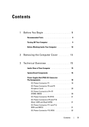
...View of Your Computer 15 System Board Components 16 Power Supply Unit (PSU) DC Connector Pin Assignments 18 DC Power Connector P1 18 DC Power Connector P2 and P3 (Graphics Card 20 DC Power Connectors P4-P7 (HDD0-HDD3 20 DC Power Connector P8 (PHY 21 DC Power Connectors P9 and P10 (Bay1 SATA and Bay2 ...SATA 21 DC Power Connector P11 and P12 (BAY and BAY2 ...
...View of Your Computer 15 System Board Components 16 Power Supply Unit (PSU) DC Connector Pin Assignments 18 DC Power Connector P1 18 DC Power Connector P2 and P3 (Graphics Card 20 DC Power Connectors P4-P7 (HDD0-HDD3 20 DC Power Connector P8 (PHY 21 DC Power Connectors P9 and P10 (Bay1 SATA and Bay2 ...SATA 21 DC Power Connector P11 and P12 (BAY and BAY2 ...
Service Manual
Page 6
9 Processor 83 Removing the Processor 83 Installing the Processor 84 10 System Board 87 Removing the System Board 87 Installing the System Board 88 11 Power Supply 91 Removing the Power Supply 91 Installing the Power Supply 92 12 Front I/O Panel 95 Removing the Front I/O Panel 95 Installing the Front I/O Panel 97 13 Master I/O Board 101 Master I/O Board Components 101 Removing the Master I/O Board 102 Installing the Master I/O Board 103 6 Contents
9 Processor 83 Removing the Processor 83 Installing the Processor 84 10 System Board 87 Removing the System Board 87 Installing the System Board 88 11 Power Supply 91 Removing the Power Supply 91 Installing the Power Supply 92 12 Front I/O Panel 95 Removing the Front I/O Panel 95 Installing the Front I/O Panel 97 13 Master I/O Board 101 Master I/O Board Components 101 Removing the Master I/O Board 102 Installing the Master I/O Board 103 6 Contents
Service Manual
Page 15
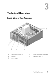
Technical Overview Inside View of Your Computer 5 1 2 3 4 1 CD/DVD drive bays (2) 3 card fan 5 power supply 2 floppy drive/media card reader 4 hard-drive bays (4) Technical Overview 15
Technical Overview Inside View of Your Computer 5 1 2 3 4 1 CD/DVD drive bays (2) 3 card fan 5 power supply 2 floppy drive/media card reader 4 hard-drive bays (4) Technical Overview 15
Service Manual
Page 18
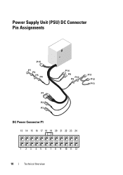
Power Supply Unit (PSU) DC Connector Pin Assignments DC Power Connector P1 13 14 15 16 17 18 19 20 21 22 23 24 1 2 3 4 5 6 7 8 9 10 11 12 18 Technical Overview
Power Supply Unit (PSU) DC Connector Pin Assignments DC Power Connector P1 13 14 15 16 17 18 19 20 21 22 23 24 1 2 3 4 5 6 7 8 9 10 11 12 18 Technical Overview
Service Manual
Page 73
... the cable into the network port or device and then plug it into your computer. 7 Connect your computer and devices to the master I/O board (see "Power Supply Unit (PSU) DC Connector Pin Assignments" on page 18). 5 Replace any full-length expansion cards that you removed (see "Installing PCI and PCI Express Cards...
... the cable into the network port or device and then plug it into your computer. 7 Connect your computer and devices to the master I/O board (see "Power Supply Unit (PSU) DC Connector Pin Assignments" on page 18). 5 Replace any full-length expansion cards that you removed (see "Installing PCI and PCI Express Cards...
Service Manual
Page 74
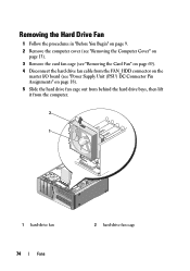
Removing the Hard Drive Fan 1 Follow the procedures in "Before You Begin" on page 9. 2 Remove the computer cover (see "Removing the Computer Cover" on page 13). 3 Remove the card fan cage (see "Removing the Card Fan" on page 69). 4 Disconnect the hard drive fan cable from the FAN_HDD connector on the master I/O board (see "Power Supply Unit (PSU) DC Connector Pin Assignments" on page 18). 5 Slide the hard drive fan cage out from behind the hard drive bays, then lift it from the computer. 2 1 1 hard-drive fan 74 Fans 2 hard-drive fan cage
Removing the Hard Drive Fan 1 Follow the procedures in "Before You Begin" on page 9. 2 Remove the computer cover (see "Removing the Computer Cover" on page 13). 3 Remove the card fan cage (see "Removing the Card Fan" on page 69). 4 Disconnect the hard drive fan cable from the FAN_HDD connector on the master I/O board (see "Power Supply Unit (PSU) DC Connector Pin Assignments" on page 18). 5 Slide the hard drive fan cage out from behind the hard drive bays, then lift it from the computer. 2 1 1 hard-drive fan 74 Fans 2 hard-drive fan cage
Service Manual
Page 77
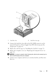
NOTICE: To connect a network cable, first plug the cable into the network port or device and then plug it into your computer. 6 Connect your computer and devices to the FAN_HDD connector on the master I/O board (see "Power Supply Unit (PSU) DC Connector Pin Assignments" on page 18). 4 Replace the card fan cage (see "Installing the Card Fan" on page 71). 5 Replace the computer cover (see "Replacing the Computer Cover" on . Fans 77 2 1 1 hard drive fan 2 hard drive fan cage 3 Connect the hard drive fan cable to electrical outlets, and then turn them on page 119).
NOTICE: To connect a network cable, first plug the cable into the network port or device and then plug it into your computer. 6 Connect your computer and devices to the FAN_HDD connector on the master I/O board (see "Power Supply Unit (PSU) DC Connector Pin Assignments" on page 18). 4 Replace the card fan cage (see "Installing the Card Fan" on page 71). 5 Replace the computer cover (see "Replacing the Computer Cover" on . Fans 77 2 1 1 hard drive fan 2 hard drive fan cage 3 Connect the hard drive fan cable to electrical outlets, and then turn them on page 119).
Service Manual
Page 91
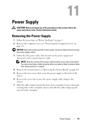
...chassis, then lift the cable clamp up and away from the computer. NOTICE: Note the location and ID of each connected power cable. Power Supply 91 Power Supply CAUTION: Before you begin any of the procedures in this section, follow the safety instructions in "Before You Begin" on...5 Remove the four screws that secure the power supply to the back of the chassis. 6 Remove the screw that stem from the power supply and disconnect each power connector before disconnecting the power supply cables. 3 Follow the DC power cables that secures the power supply cable clamp to the chassis. 7 Slide ...
...chassis, then lift the cable clamp up and away from the computer. NOTICE: Note the location and ID of each connected power cable. Power Supply 91 Power Supply CAUTION: Before you begin any of the procedures in this section, follow the safety instructions in "Before You Begin" on...5 Remove the four screws that secure the power supply to the back of the chassis. 6 Remove the screw that stem from the power supply and disconnect each power connector before disconnecting the power supply cables. 3 Follow the DC power cables that secures the power supply cable clamp to the chassis. 7 Slide ...
Service Manual
Page 92
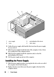
...the Power Supply 1 Slide the power supply into place, ensuring that secure the power supply to clear the protruding lip of the chassis. 11 Lift the power supply up and out of the computer chassis. 92 Power Supply 1 2 3 4 1 power supply 3 screw 2 protruding lip of the chassis 4 cable clamp 8 Gather the power supply cable...Replace the four screws that the tabs on the computer chassis. 10 Slide the power supply towards the front of the computer, to free it from the power supply, for easy removal. 9 Slide the power supply towards the expansion cards, to the back of the computer.
...the Power Supply 1 Slide the power supply into place, ensuring that secure the power supply to clear the protruding lip of the chassis. 11 Lift the power supply up and out of the computer chassis. 92 Power Supply 1 2 3 4 1 power supply 3 screw 2 protruding lip of the chassis 4 cable clamp 8 Gather the power supply cable...Replace the four screws that the tabs on the computer chassis. 10 Slide the power supply towards the front of the computer, to free it from the power supply, for easy removal. 9 Slide the power supply towards the expansion cards, to the back of the computer.
Service Manual
Page 93
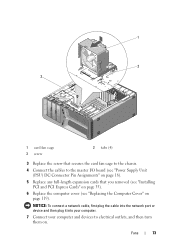
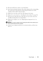
3 Reroute the DC power cables as you found them. 4 Insert the tab along the bottom of the cable clamp into ...secures the cable clamp to electrical outlets, and then turn them . 8 Replace the computer cover (see "Replacing the Computer Cover" on . Power Supply 93 NOTICE: To connect a network cable, first plug the cable into the network port or device and then plug it snaps into the .... 6 Replace the system board (see "Installing the System Board" on page 88). 7 Reattach each of the DC power cables that were previously connected, carefully rerouting them as you found them on page 119).
3 Reroute the DC power cables as you found them. 4 Insert the tab along the bottom of the cable clamp into ...secures the cable clamp to electrical outlets, and then turn them . 8 Replace the computer cover (see "Replacing the Computer Cover" on . Power Supply 93 NOTICE: To connect a network cable, first plug the cable into the network port or device and then plug it snaps into the .... 6 Replace the system board (see "Installing the System Board" on page 88). 7 Reattach each of the DC power cables that were previously connected, carefully rerouting them as you found them on page 119).


