Owner's Manual
Page 4
... Replacing the Optical Drive 27 Procedure 27 Postrequisites 27 14 Removing the Memory Module(s 28 Prerequisites 28 Procedure 28 15 Replacing the Memory Module(s 30 Procedure 30 Postrequisites 30 16 Removing the System-Board Shield 31 Prerequisites 31 Procedure 31 17 Replacing the System-Board Shield 32 Procedure 32 Postrequisites 32 18 Removing the Power-Supply Fan 33 Prerequisites 33 Procedure 33 19 Replacing the Power-Supply Fan...
... Replacing the Optical Drive 27 Procedure 27 Postrequisites 27 14 Removing the Memory Module(s 28 Prerequisites 28 Procedure 28 15 Replacing the Memory Module(s 30 Procedure 30 Postrequisites 30 16 Removing the System-Board Shield 31 Prerequisites 31 Procedure 31 17 Replacing the System-Board Shield 32 Procedure 32 Postrequisites 32 18 Removing the Power-Supply Fan 33 Prerequisites 33 Procedure 33 19 Replacing the Power-Supply Fan...
Owner's Manual
Page 7
... 42 Removing the Wireless Keyboard/Mouse Receiver 61 Prerequisites 61 Procedure 62 43 Replacing the Wireless Keyboard/Mouse Receiver 63 Procedure 63 Postrequisites 63 44 Removing the Speakers 64 Prerequisites 64 Procedure 65 45 Replacing the Speakers 66 Procedure 66 Postrequisites 66 46 Removing the I/O-Board 67 Prerequisites 67 Procedure 68 47 Replacing the I/O Board 70 Procedure 70 Postrequisites 70 48 Removing the Antenna Modules 71...
... 42 Removing the Wireless Keyboard/Mouse Receiver 61 Prerequisites 61 Procedure 62 43 Replacing the Wireless Keyboard/Mouse Receiver 63 Procedure 63 Postrequisites 63 44 Removing the Speakers 64 Prerequisites 64 Procedure 65 45 Replacing the Speakers 66 Procedure 66 Postrequisites 66 46 Removing the I/O-Board 67 Prerequisites 67 Procedure 68 47 Replacing the I/O Board 70 Procedure 70 Postrequisites 70 48 Removing the Antenna Modules 71...

Owner's Manual
Page 8
... 75 51 Replacing the Power-Button Assembly . . . . . 76 Procedure 76 Postrequisites 76 52 Removing the System Board 77 Prerequisites 77 Procedure 78 53 Replacing the System Board 79 Procedure 79 Postrequisites 79 Entering the Service Tag in system setup 80 54 Removing the Side I/O-Board 81 Prerequisites 81 Procedure 82 55 Replacing the Side-I/O Board 83 Procedure 83 Postrequisites 83 56 Removing the Middle Cover 84...
... 75 51 Replacing the Power-Button Assembly . . . . . 76 Procedure 76 Postrequisites 76 52 Removing the System Board 77 Prerequisites 77 Procedure 78 53 Replacing the System Board 79 Procedure 79 Postrequisites 79 Entering the Service Tag in system setup 80 54 Removing the Side I/O-Board 81 Prerequisites 81 Procedure 82 55 Replacing the Side-I/O Board 83 Procedure 83 Postrequisites 83 56 Removing the Middle Cover 84...
Owner's Manual
Page 9
... 59 Replacing the Display Panel 96 Procedure 96 Postrequisites 97 60 Removing the Camera Module 98 Prerequisites 98 Procedure 99 61 Replacing the Camera Module 100 Procedure 100 Postrequisites 100 62 Removing the Microphone Modules 101 Prerequisites 101 Procedure 102 63 Replacing the Microphone Modules 103 Procedure Postrequisites 103 103 64 System Setup 104 Overview 104 Entering System Setup 104 Changing Boot Sequence 110 Clearing Forgotten Passwords 111 Clearing CMOS Settings 112 65 Flashing the BIOS 113...
... 59 Replacing the Display Panel 96 Procedure 96 Postrequisites 97 60 Removing the Camera Module 98 Prerequisites 98 Procedure 99 61 Replacing the Camera Module 100 Procedure 100 Postrequisites 100 62 Removing the Microphone Modules 101 Prerequisites 101 Procedure 102 63 Replacing the Microphone Modules 103 Procedure Postrequisites 103 103 64 System Setup 104 Overview 104 Entering System Setup 104 Changing Boot Sequence 110 Clearing Forgotten Passwords 111 Clearing CMOS Settings 112 65 Flashing the BIOS 113...

Owner's Manual
Page 11
...: If you are using a different operating system, see the Regulatory Compliance Homepage at the back of the screen to open the Charms sidebar, and then click Settings→ Power→ Shut down instructions. 3 Disconnect your computer and all attached devices from their edges and avoid touching pins and contacts. Before You Begin Turn Off Your Computer and Connected Devices CAUTION: To avoid...
...: If you are using a different operating system, see the Regulatory Compliance Homepage at the back of the screen to open the Charms sidebar, and then click Settings→ Power→ Shut down instructions. 3 Disconnect your computer and all attached devices from their edges and avoid touching pins and contacts. Before You Begin Turn Off Your Computer and Connected Devices CAUTION: To avoid...
Owner's Manual
Page 13
Failure to their electrical outlets. CAUTION: Before turning on your computer. • Connect your computer and all screws and ensure that no stray screws remain inside your computer. • Connect any external devices, cables, cards, and any other part(s) you removed before working on your computer, replace all attached devices to do so may damage your computer. After Working Inside Your Computer | 13 After...
Failure to their electrical outlets. CAUTION: Before turning on your computer. • Connect your computer and all screws and ensure that no stray screws remain inside your computer. • Connect any external devices, cables, cards, and any other part(s) you removed before working on your computer, replace all attached devices to do so may damage your computer. After Working Inside Your Computer | 13 After...

Owner's Manual
Page 14
... Begin" on page 13. Inside View of Your Computer 4 3 2 1 5 67 8 9 16 15 14 1 power-button assembly 3 optical-drive assembly 5 hard-drive assembly 7 processor heat-sink fan 9 wireless mini-card 11 system board 13 coin-cell battery 15 I/O panel 10 11 12 13 2 converter board 4 power-supply unit 6 cooling vents 8 processor heat-sink 10 memory module(s) 12 mSATA mini-card 14 trim cover 16 power-supply fan 14 | Technical Overview
... Begin" on page 13. Inside View of Your Computer 4 3 2 1 5 67 8 9 16 15 14 1 power-button assembly 3 optical-drive assembly 5 hard-drive assembly 7 processor heat-sink fan 9 wireless mini-card 11 system board 13 coin-cell battery 15 I/O panel 10 11 12 13 2 converter board 4 power-supply unit 6 cooling vents 8 processor heat-sink 10 memory module(s) 12 mSATA mini-card 14 trim cover 16 power-supply fan 14 | Technical Overview
Owner's Manual
Page 29
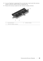
3 Use your fingertips to spread apart the securing clips on each end of the memory module connector until the memory module pops up. 4 Remove the memory module from the memory-module connector. 3 1 2 1 securing-clips (2) 3 memory-module connector 2 memory module Removing the Memory Module(s) | 29
3 Use your fingertips to spread apart the securing clips on each end of the memory module connector until the memory module pops up. 4 Remove the memory module from the memory-module connector. 3 1 2 1 securing-clips (2) 3 memory-module connector 2 memory module Removing the Memory Module(s) | 29

Owner's Manual
Page 30
... the instructions in "After Working Inside Your Computer" on page 11. See "Replacing the Back Cover" on page 18. 2 Follow the instructions in "After Working Inside Your Computer" on the memory-module shield into place. NOTE: If you do not hear the click, remove the memory module and reinstall it clicks into the slots on the system-board shield and slide the memory-module toward...
... the instructions in "After Working Inside Your Computer" on page 11. See "Replacing the Back Cover" on page 18. 2 Follow the instructions in "After Working Inside Your Computer" on the memory-module shield into place. NOTE: If you do not hear the click, remove the memory module and reinstall it clicks into the slots on the system-board shield and slide the memory-module toward...
Owner's Manual
Page 42
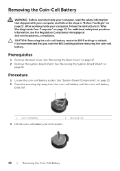
... clip 3 Lift the coin-cell battery out of its socket. 42 | Removing the Coin-Cell Battery CAUTION: Removing the coin-cell battery resets the BIOS settings to default. Procedure 1 Locate the coin-cell battery socket. See "System-Board Components" on page 17. 2 Remove the system-board shield. See "Removing the System-Board Shield" on page 13. Removing the Coin-Cell Battery WARNING: Before working inside your computer and follow...
... clip 3 Lift the coin-cell battery out of its socket. 42 | Removing the Coin-Cell Battery CAUTION: Removing the coin-cell battery resets the BIOS settings to default. Procedure 1 Locate the coin-cell battery socket. See "System-Board Components" on page 17. 2 Remove the system-board shield. See "Removing the System-Board Shield" on page 13. Removing the Coin-Cell Battery WARNING: Before working inside your computer and follow...

Owner's Manual
Page 46
... that shipped with the tab on the mini-card WLAN + Bluetooth (2 cables) Main WLAN + Bluetooth (white triangle) Auxiliary WLAN + Bluetooth (black triangle) Wireless-antenna cable color schemes white black Postrequisites 1 Replace the system-board shield. See "Replacing the Back Cover" on page 18. 3 Follow the instructions in "Before You Begin" on page 32. 2 Replace the back cover. After working inside your computer, follow the steps in "After...
... that shipped with the tab on the mini-card WLAN + Bluetooth (2 cables) Main WLAN + Bluetooth (white triangle) Auxiliary WLAN + Bluetooth (black triangle) Wireless-antenna cable color schemes white black Postrequisites 1 Replace the system-board shield. See "Replacing the Back Cover" on page 18. 3 Follow the instructions in "Before You Begin" on page 32. 2 Replace the back cover. After working inside your computer, follow the steps in "After...
Owner's Manual
Page 77
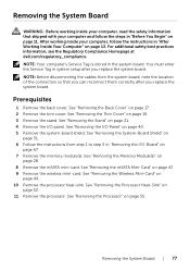
... dell.com/regulatory_compliance. See "Removing the Memory Module(s)" on page 55. You must enter the Service Tag in system setup after you replace the system board. See "Removing the Processor Heat-Sink" on page 19. 3 Remove the stand. NOTE: Before disconnecting the cables from step 1 to step 5 in the system board. See "Removing the Trim Cover" on page 53. 11 Remove the processor. See "Removing the Wireless Mini-Card...
... dell.com/regulatory_compliance. See "Removing the Memory Module(s)" on page 55. You must enter the Service Tag in system setup after you replace the system board. See "Removing the Processor Heat-Sink" on page 19. 3 Remove the stand. NOTE: Before disconnecting the cables from step 1 to step 5 in the system board. See "Removing the Trim Cover" on page 53. 11 Remove the processor. See "Removing the Wireless Mini-Card...

Owner's Manual
Page 80
See "System Setup Options" on the computer. 2 Press during POST to enter the system setup program. 3 Navigate to the Main tab and enter the Service Tag in system setup 1 Turn on page 105. 80 | Replacing the System Board Entering the Service Tag in the Service Tag Input field.
See "System Setup Options" on the computer. 2 Press during POST to enter the system setup program. 3 Navigate to the Main tab and enter the Service Tag in system setup 1 Turn on page 105. 80 | Replacing the System Board Entering the Service Tag in the Service Tag Input field.

Owner's Manual
Page 104
... the amount of RAM, the size of the hard drive, and so on. • Change the system setup configurations. • Set or change a user-selectable option, such as the user password, type of hard drive installed, enabling or disabling base devices, and so on (or restart) your computer. 2 During POST, when the DELL logo is lost. NOTE: Before you press before the F2 prompt, this keystroke is displayed, watch for it...
... the amount of RAM, the size of the hard drive, and so on. • Change the system setup configurations. • Set or change a user-selectable option, such as the user password, type of hard drive installed, enabling or disabling base devices, and so on (or restart) your computer. 2 During POST, when the DELL logo is lost. NOTE: Before you press before the F2 prompt, this keystroke is displayed, watch for it...
Owner's Manual
Page 105
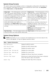
... computer only if the Service Tag is divided into three areas: the setup item, active help screen, and key functions. System Setup Options NOTE: Depending on the screen is not present. Displays the current time. Scroll up - Displays the BIOS release date. System Setup Screens The system setup screen displays current or changeable configuration information for your computer. Information on your computer and installed devices, the items listed in this field you...
... computer only if the Service Tag is divided into three areas: the setup item, active help screen, and key functions. System Setup Options NOTE: Depending on the screen is not present. Displays the current time. Scroll up - Displays the BIOS release date. System Setup Screens The system setup screen displays current or changeable configuration information for your computer. Information on your computer and installed devices, the items listed in this field you...

Owner's Manual
Page 107
... If enabled, a Virtual Machine Monitor (VMM) can access your computer. NOTE: Windows 8 enables this feature even if this feature is set to use all cores available in the processor. Intel(R) Turbo Boost Technology If enabled, allows your computer. Advanced→ USB Configuration Rear USB Ports Allows you to configure the integrated hard drive controller to enable or disable the USB ports at the side of your computer to disabled. System Setup | 107...
... If enabled, a Virtual Machine Monitor (VMM) can access your computer. NOTE: Windows 8 enables this feature even if this feature is set to use all cores available in the processor. Intel(R) Turbo Boost Technology If enabled, allows your computer. Advanced→ USB Configuration Rear USB Ports Allows you to configure the integrated hard drive controller to enable or disable the USB ports at the side of your computer to disabled. System Setup | 107...

Owner's Manual
Page 108
... Boot→ Clear Secure Boot Database Manage All Keys (PK, KEK, Displays the keys in the UEFI boot mode. 1st Boot Displays the first boot device. 2nd Boot Displays the second boot device. 3rd Boot Displays the third boot device. 4th Boot Displays the fourth boot device. 5th Boot Displays the fifth boot device. Power Wake Up by Integrated LAN/WLAN If enabled, will wake the system using a network message. Boot→ Boot Settings Configuration Numlock Key Select power-on state for numlock. Keyboard Errors Displays keyboard-related errors during boot. USB Boot Support...
... Boot→ Clear Secure Boot Database Manage All Keys (PK, KEK, Displays the keys in the UEFI boot mode. 1st Boot Displays the first boot device. 2nd Boot Displays the second boot device. 3rd Boot Displays the third boot device. 4th Boot Displays the fourth boot device. 5th Boot Displays the fifth boot device. Power Wake Up by Integrated LAN/WLAN If enabled, will wake the system using a network message. Boot→ Boot Settings Configuration Numlock Key Select power-on state for numlock. Keyboard Errors Displays keyboard-related errors during boot. USB Boot Support...

Owner's Manual
Page 109
... Changes and Reset Load Default If the supervisor password is set a supervisor password. Allows you to enable or disable TPM PPI deprovision override. Allows you to set the auto power-on mode. Allows you to load the default BIOS settings. Displays the status of the user password. Displays the status of the supervisor password. Allows you to configure when the computer prompts for passwords. (When entering system setup or at a pre-configured time. If enabled, clears...
... Changes and Reset Load Default If the supervisor password is set a supervisor password. Allows you to enable or disable TPM PPI deprovision override. Allows you to set the auto power-on mode. Allows you to load the default BIOS settings. Displays the status of the user password. Displays the status of the supervisor password. Allows you to configure when the computer prompts for passwords. (When entering system setup or at a pre-configured time. If enabled, clears...

Owner's Manual
Page 110
... again. Changing Boot Sequence for example, to boot from the Drivers and Utilities disc. NOTE: Write down your current boot sequence in the lower-right corner of the device. 110 | System Setup Then shut down -arrow keys to move through the list of devices. 4 Press plus (+) or minus (-) to a USB port. 2 Turn on page 104. 2 Use the arrow keys to highlight the Boot menu option and press to run Dell Diagnostics...
... again. Changing Boot Sequence for example, to boot from the Drivers and Utilities disc. NOTE: Write down your current boot sequence in the lower-right corner of the device. 110 | System Setup Then shut down -arrow keys to move through the list of devices. 4 Press plus (+) or minus (-) to a USB port. 2 Turn on page 104. 2 Use the arrow keys to highlight the Boot menu option and press to run Dell Diagnostics...
Owner's Manual
Page 115
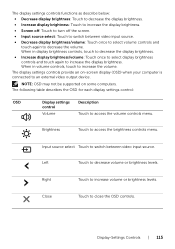
... computers. Close Touch to an external video output device. The display settings controls functions as describe below: • Decrease display brightness: Touch to decrease the display brightness. • Increase display brightness: Touch to increase the display brightness. • Screen off: Touch to turn off the screen. • Input source select: Touch to switch between video input source. When in display brightness controls, touch to decrease the display brightness. • Increase display brightness/volume: Touch once to select display brightness controls and touch again to...
... computers. Close Touch to an external video output device. The display settings controls functions as describe below: • Decrease display brightness: Touch to decrease the display brightness. • Increase display brightness: Touch to increase the display brightness. • Screen off: Touch to turn off the screen. • Input source select: Touch to switch between video input source. When in display brightness controls, touch to decrease the display brightness. • Increase display brightness/volume: Touch once to select display brightness controls and touch again to...


