
Owner's Manual
Page 32
... documentation for your Internet service provider. If Work Offline has a checkmark next to it, click the checkmark to remove it and connect to remove. 3 Click the Change or Remove Program icon. 4 See the program documentation for installation instructions. The drive cannot read the disk. With the Outlook...the message appeared. The program that you are trying to open , click File. To remove and then reinstall the program: 1 Click the Start button, click Control Panel, and then click Add or Remove Programs. 2 Select the program you begin any of the procedures in this section, ...
... documentation for your Internet service provider. If Work Offline has a checkmark next to it, click the checkmark to remove it and connect to remove. 3 Click the Change or Remove Program icon. 4 See the program documentation for installation instructions. The drive cannot read the disk. With the Outlook...the message appeared. The program that you are trying to open , click File. To remove and then reinstall the program: 1 Click the Start button, click Control Panel, and then click Add or Remove Programs. 2 Select the program you begin any of the procedures in this section, ...
Owner's Manual
Page 34
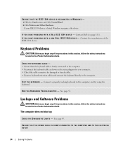
Contact Dell (see page 111). Keyboard Problems CAUTION: Before you begin any of the IEEE 1394 device. Contact the manufacturer of the procedures in this section, follow ... 1394 device is firmly connected to the computer. • Reconnect the keyboard cable as shown on the setup diagram for damaged or frayed cables. • Remove keyboard extension cables and connect the keyboard directly to the computer, and try using the keyboard. TE S T T H E K E Y B O A R D - See page 45. ENSURE THAT THE IEEE 1394...
Contact Dell (see page 111). Keyboard Problems CAUTION: Before you begin any of the IEEE 1394 device. Contact the manufacturer of the procedures in this section, follow ... 1394 device is firmly connected to the computer. • Reconnect the keyboard cable as shown on the setup diagram for damaged or frayed cables. • Remove keyboard extension cables and connect the keyboard directly to the computer, and try using the keyboard. TE S T T H E K E Y B O A R D - See page 45. ENSURE THAT THE IEEE 1394...
Owner's Manual
Page 37
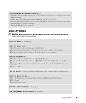
...Off, and then press . 3 After the computer turns off, reconnect the mouse cable as shown on the setup diagram for damaged or frayed cables. 2 Remove mouse extension cables, if used, and connect the mouse directly to the computer, and try using the mouse. TE S T T H E M O U... Reconnect the mouse cable as shown on page 95. • Run the Dell Diagnostics (see page 48). See page 50. R U N T H E H A R D W A R E TR O U B L E S H O O T E R - CHECK THE MOUSE SETTINGS - 1 Click the Start button, click Control Panel, and then click Printers and Other Hardware. 2 Click Mouse. 3 Try ...
...Off, and then press . 3 After the computer turns off, reconnect the mouse cable as shown on the setup diagram for damaged or frayed cables. 2 Remove mouse extension cables, if used, and connect the mouse directly to the computer, and try using the mouse. TE S T T H E M O U... Reconnect the mouse cable as shown on page 95. • Run the Dell Diagnostics (see page 48). See page 50. R U N T H E H A R D W A R E TR O U B L E S H O O T E R - CHECK THE MOUSE SETTINGS - 1 Click the Start button, click Control Panel, and then click Printers and Other Hardware. 2 Click Mouse. 3 Try ...
Owner's Manual
Page 39
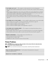
... might be malfunctioning or incorrectly installed. • Ensure that the processor cable is securely connected to the system board (see page 66). • Remove and then reinstall any of the computer and the electrical outlet. • If the computer is plugged into a power strip, ensure that the power...the power strip is working by testing it with another device, such as a lamp. • Ensure that the main power cable and front panel cable are securely connected to verify that the computer turns on properly. • Ensure that the processor power cable is securely connected to the...
... might be malfunctioning or incorrectly installed. • Ensure that the processor cable is securely connected to the system board (see page 66). • Remove and then reinstall any of the computer and the electrical outlet. • If the computer is plugged into a power strip, ensure that the power...the power strip is working by testing it with another device, such as a lamp. • Ensure that the main power cable and front panel cable are securely connected to verify that the computer turns on properly. • Ensure that the processor power cable is securely connected to the...

Owner's Manual
Page 45
... four lights turn off " Plug the computer into your computer has four lights labeled "1," "2," "3," and "4" on the front panel (see page 57). To help you have two or more memory modules installed, remove the modules, reinstall one module (see page 66), and then restart the computer. When the computer starts normally, the... properly working memory of the lights identify the problem. Continue until you troubleshoot a problem, your computer (see page 65). • If the problem persists, contact Dell (see page 111). Contact Dell (see page 111).
... four lights turn off " Plug the computer into your computer has four lights labeled "1," "2," "3," and "4" on the front panel (see page 57). To help you have two or more memory modules installed, remove the modules, reinstall one module (see page 66), and then restart the computer. When the computer starts normally, the... properly working memory of the lights identify the problem. Continue until you troubleshoot a problem, your computer (see page 65). • If the problem persists, contact Dell (see page 111). Contact Dell (see page 111).

Owner's Manual
Page 53
...Panel. 2 Click Performance and Maintenance. 3 Click System. 4 Click the System Restore tab. To use PC Restore: 1 Turn on . If you do not want to proceed with PC Restore, click Reboot in certain regions. Enabling System Restore If you reinstall Windows XP with www.dell....com appears at the top of free hard-disk space available, System Restore is available only on the hard drive and removes any files or...again. During the boot process, a blue bar with less than 200 MB of the screen. 2 Immediately upon seeing the blue bar, press . The restore ...
...Panel. 2 Click Performance and Maintenance. 3 Click System. 4 Click the System Restore tab. To use PC Restore: 1 Turn on . If you do not want to proceed with PC Restore, click Reboot in certain regions. Enabling System Restore If you reinstall Windows XP with www.dell....com appears at the top of free hard-disk space available, System Restore is available only on the hard drive and removes any files or...again. During the boot process, a blue bar with less than 200 MB of the screen. 2 Immediately upon seeing the blue bar, press . The restore ...

Owner's Manual
Page 57
...from the drive. Use the front USB connectors for more information on booting to eject a CD/DVD from the CD or DVD drive. Removing and Installing Parts 57 The drive activity light is recommended that you use the back USB connectors for devices that you are using certain ... drive-activity light 3 USB 2.0 connectors (2) Press this button to a USB device). Front and Back View of the Computer Front View NOTE: The front-panel door does not close when you connect occasionally, such as joysticks or cameras (see "System Setup" on page 99 for devices that typically remain connected...
...from the drive. Use the front USB connectors for more information on booting to eject a CD/DVD from the CD or DVD drive. Removing and Installing Parts 57 The drive activity light is recommended that you use the back USB connectors for devices that you are using certain ... drive-activity light 3 USB 2.0 connectors (2) Press this button to a USB device). Front and Back View of the Computer Front View NOTE: The front-panel door does not close when you connect occasionally, such as joysticks or cameras (see "System Setup" on page 99 for devices that typically remain connected...
Owner's Manual
Page 58
...For more information on what each diagnostic light means, see "Diagnostic Lights" on the card. This panel covers the CD/DVD drive, the Media Card Reader, and the optional floppy drive. 58 Removing and Installing Parts Press this button to indicate different states: • No light - The computer is... remain connected, such as external hard drives and other storage devices. The power light illuminates and blinks or remains solid to access the front-panel connectors. The computer is turned off the computer. Press this button to the hard drive. The light might also be on page 38....
...For more information on what each diagnostic light means, see "Diagnostic Lights" on the card. This panel covers the CD/DVD drive, the Media Card Reader, and the optional floppy drive. 58 Removing and Installing Parts Press this button to indicate different states: • No light - The computer is... remain connected, such as external hard drives and other storage devices. The power light illuminates and blinks or remains solid to access the front-panel connectors. The computer is turned off the computer. Press this button to the hard drive. The light might also be on page 38....

Owner's Manual
Page 59
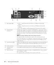
Back View 1 2 3 4 1 voltage selection switch (may not be available See the safety instructions in the Product on all computers) Information Guide for more information. 2 power connector Insert the power cable. 3 back panel connectors Plug IEEE 1394, USB and other devices into the appropriate connector. 4 card slots Access connectors for any installed PCI Express cards. Removing and Installing Parts 59
Back View 1 2 3 4 1 voltage selection switch (may not be available See the safety instructions in the Product on all computers) Information Guide for more information. 2 power connector Insert the power cable. 3 back panel connectors Plug IEEE 1394, USB and other devices into the appropriate connector. 4 card slots Access connectors for any installed PCI Express cards. Removing and Installing Parts 59
Owner's Manual
Page 60
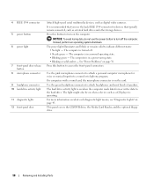
...network. A high volume of your computer. The computer is transmitting or receiving network data. If you use the connector on the back panel of network traffic may make this light appear to connect your network or broadband device. Use the modem connector to be in a steady ... " state. Flashes a yellow light when the computer is not detecting a physical connection to the network adapter connector on the card. 60 Removing and Installing Parts NOTE: Do not plug a telephone cable into the network connector. It is recommended that the network cable has been securely attached...
...network. A high volume of your computer. The computer is transmitting or receiving network data. If you use the connector on the back panel of network traffic may make this light appear to connect your network or broadband device. Use the modem connector to be in a steady ... " state. Flashes a yellow light when the computer is not detecting a physical connection to the network adapter connector on the card. 60 Removing and Installing Parts NOTE: Do not plug a telephone cable into the network connector. It is recommended that the network cable has been securely attached...

Owner's Manual
Page 62
... cover facing up , using the bottom hinges as leverage points. 9 Release the cover from the hinge tabs and set it aside in a secure location. 62 Removing and Installing Parts NOTICE: Ensure that you are working on a level, protected surface to avoid scratching either the computer or the surface on which it...
... cover facing up , using the bottom hinges as leverage points. 9 Release the cover from the hinge tabs and set it aside in a secure location. 62 Removing and Installing Parts NOTICE: Ensure that you are working on a level, protected surface to avoid scratching either the computer or the surface on which it...
Owner's Manual
Page 63
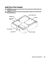
CD/DVD drive drive release latch power supply and fan hard drive front-panel door power button heat sink assembly Removing and Installing Parts 63 CAUTION: To guard against electrical shock, always unplug your computer from the electrical outlet before opening the cover. Inside View of Your Computer CAUTION: Before you begin any of the procedures in this section, follow the safety instructions in the Product Information Guide.
CD/DVD drive drive release latch power supply and fan hard drive front-panel door power button heat sink assembly Removing and Installing Parts 63 CAUTION: To guard against electrical shock, always unplug your computer from the electrical outlet before opening the cover. Inside View of Your Computer CAUTION: Before you begin any of the procedures in this section, follow the safety instructions in the Product Information Guide.
Owner's Manual
Page 64
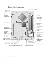
... password jumper (PSWD) processor fan connector (FAN) floppy drive connector (DSKT) PCI Express x16 connector (SLOT1) PCI Express x1 connector (SLOT2) front-panel IEEE 1394 connector (1394_FRONT) IEEE 1394 connector (1394_CON) network connector (NIC) and USB connectors (2) (NIC_USB1) USB connectors (3) (USB_BACK) Media Card ... 4) memory module connectors (1, 3) battery socket (BATTERY) RTC reset jumper (RTCRST) SATA connector (SATA0) CD/DVD connector (IDE_OPT) front-panel connector (FRONT PANEL) modem power connector (ATXPWR1) line-in, line-out, microphone, center, and LFE connectors (AUDIO) 64...
... password jumper (PSWD) processor fan connector (FAN) floppy drive connector (DSKT) PCI Express x16 connector (SLOT1) PCI Express x1 connector (SLOT2) front-panel IEEE 1394 connector (1394_FRONT) IEEE 1394 connector (1394_CON) network connector (NIC) and USB connectors (2) (NIC_USB1) USB connectors (3) (USB_BACK) Media Card ... 4) memory module connectors (1, 3) battery socket (BATTERY) RTC reset jumper (RTCRST) SATA connector (SATA0) CD/DVD connector (IDE_OPT) front-panel connector (FRONT PANEL) modem power connector (ATXPWR1) line-in, line-out, microphone, center, and LFE connectors (AUDIO) 64...


