
User Manual
Page 1
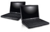
camera status light 4. Windows Mobility Center 6. Dell Support Center 7. Front View 1. microphone 2. network connector Regulatory Model : P18S Regulatory Type : P18S001 2011 - 05 camera 3. Dell Vostro V131 Setup And Features Information About Warnings WARNING: A WARNING indicates a potential for property damage, personal injury, or death. display 5. Front And Back Figure 1. Dell Instant Launch Manager 8.
camera status light 4. Windows Mobility Center 6. Dell Support Center 7. Front View 1. microphone 2. network connector Regulatory Model : P18S Regulatory Type : P18S001 2011 - 05 camera 3. Dell Vostro V131 Setup And Features Information About Warnings WARNING: A WARNING indicates a potential for property damage, personal injury, or death. display 5. Front And Back Figure 1. Dell Instant Launch Manager 8.

User Manual
Page 2
... indicate a problem with USB PowerShare 6. USB 3.0 connectors (2) 11. headphone and microphone combo connector 12. USB 2.0 connector with the fan or the computer. 2 The computer turns on the fan when the computer gets hot. fingerprint reader 13. Back View 1. HDMI connector 5. security cable slot 2. cooling vents 7. Restricting the airflow can damage the computer or cause a fire. 9. device status lights 17. Fan noise is running. VGA connector 10. touchpad disable LED 18. power button...
... indicate a problem with USB PowerShare 6. USB 3.0 connectors (2) 11. headphone and microphone combo connector 12. USB 2.0 connector with the fan or the computer. 2 The computer turns on the fan when the computer gets hot. fingerprint reader 13. Back View 1. HDMI connector 5. security cable slot 2. cooling vents 7. Restricting the airflow can damage the computer or cause a fire. 9. device status lights 17. Fan noise is running. VGA connector 10. touchpad disable LED 18. power button...
User Manual
Page 3
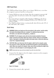
..., power connectors and power strips vary among countries. Connect the AC adapter to the AC adapter connector on the AC adapter to avoid damaging the cable. Connect the network cable (optional). 3 USB PowerShare The USB PowerShare feature allows you to charge USB devices, even when the computer is powered on/off or in sleep state. • Certain USB devices may cause fire or equipment damage. Using an incompatible cable or improperly connecting the cable...
..., power connectors and power strips vary among countries. Connect the AC adapter to the AC adapter connector on the AC adapter to avoid damaging the cable. Connect the network cable (optional). 3 USB PowerShare The USB PowerShare feature allows you to charge USB devices, even when the computer is powered on/off or in sleep state. • Certain USB devices may cause fire or equipment damage. Using an incompatible cable or improperly connecting the cable...

User Manual
Page 4
.... USB Connector 4. For more information regarding the configuration of your computer, click Start → Help and Support and select the option to ship with your computer at least once before you install any cards or connect the computer to turn on and shut down your computer. Figure 6. Open the computer display and press the power button to a docking device or other external device, such as a mouse or keyboard (optional). Power Button...
.... USB Connector 4. For more information regarding the configuration of your computer, click Start → Help and Support and select the option to ship with your computer at least once before you install any cards or connect the computer to turn on and shut down your computer. Figure 6. Open the computer display and press the power button to a docking device or other external device, such as a mouse or keyboard (optional). Power Button...

Owners Manual
Page 5
... (I/O) Board 66 24 Removing the DC-In Port 67 Installing The DC-In Port 69 25 Removing The LVDS Cable 71 Installing The Low-Voltage Differential Signalling (LVDS) Cable 72 26 System Setup 73 System Setup Overview 73 Entering System Setup...73 System Setup Screens...73 System Setup Menu Options 75 27 Diagnostics 79 Device Status Lights...79 LED Status...79 Diagnostic Beep Codes 80 Keyboard Status Lights 82 28 Technical Specifications 83 29 Contacting Dell...
... (I/O) Board 66 24 Removing the DC-In Port 67 Installing The DC-In Port 69 25 Removing The LVDS Cable 71 Installing The Low-Voltage Differential Signalling (LVDS) Cable 72 26 System Setup 73 System Setup Overview 73 Entering System Setup...73 System Setup Screens...73 System Setup Menu Options 75 27 Diagnostics 79 Device Status Lights...79 LED Status...79 Diagnostic Beep Codes 80 Keyboard Status Lights 82 28 Technical Specifications 83 29 Contacting Dell...

Owners Manual
Page 7
... on its connector or on the locking tabs before you connect a cable, ensure that is not authorized by Dell is not covered by its edges, not by the online or telephone service and support team. CAUTION: When you disconnect the cable. Read and follow the safety instructions that shipped with the product. WARNING: Before working inside your computer, read the...
... on its connector or on the locking tabs before you connect a cable, ensure that is not authorized by Dell is not covered by its edges, not by the online or telephone service and support team. CAUTION: When you disconnect the cable. Read and follow the safety instructions that shipped with the product. WARNING: Before working inside your computer, read the...

Owners Manual
Page 8
... the optional Media Base or Battery Slice, undock it. Turn off your computer from being scratched. 2. Open the display. 10. Press the power button to dissipate static electricity, which could harm internal components. 11. Remove any installed ExpressCards or Smart Cards from their electrical outlets. 6. Turn the computer top-side up. 9. Disconnect your computer and all network cables from the network device. 4. Ensure that your work surface is connected...
... the optional Media Base or Battery Slice, undock it. Turn off your computer from being scratched. 2. Open the display. 10. Press the power button to dissipate static electricity, which could harm internal components. 11. Remove any installed ExpressCards or Smart Cards from their electrical outlets. 6. Turn the computer top-side up. 9. Disconnect your computer and all network cables from the network device. 4. Ensure that your work surface is connected...

Owners Manual
Page 9
... your operating system, press and hold the power button for this particular Dell computer. • #0 Phillips screwdriver • #1 Phillips screwdriver • Small plastic scribe • Flash BIOS update program CD Turning Off Your Computer CAUTION: To avoid losing data, save and close all open programs before turning on your computer. 1. Connect any external devices, such as a port replicator, battery slice, or media base, and replace any external devices, cards, and cables...
... your operating system, press and hold the power button for this particular Dell computer. • #0 Phillips screwdriver • #1 Phillips screwdriver • Small plastic scribe • Flash BIOS update program CD Turning Off Your Computer CAUTION: To avoid losing data, save and close all open programs before turning on your computer. 1. Connect any external devices, such as a port replicator, battery slice, or media base, and replace any external devices, cards, and cables...

Owners Manual
Page 21
Removing The Memory 7 1. Remove the battery. 3. Remove the memory module from the memory module till the memory module pops up. 5. Pry the retention clips away from the computer. 21 Remove the base cover. 4. Follow the procedures in Before Working On Your Computer. 2.
Removing The Memory 7 1. Remove the battery. 3. Remove the memory module from the memory module till the memory module pops up. 5. Pry the retention clips away from the computer. 21 Remove the base cover. 4. Follow the procedures in Before Working On Your Computer. 2.

Owners Manual
Page 24
Remove the screws which secure the hard-drive bracket to the computer. 5. Replace and tighten the screw to secure the hard drive to the hard drive. Install the base cover. 6. Install the battery. 7. Installing The Hard Drive 1. Separate the hard drive bracket from the hard drive. Align the hard-drive bracket with the hard drive. 2. Slide the hard drive into the bay on the hard drive to secure the hard drive bracket to the hard drive. 3. 7. Follow the procedures in After Working Inside Your Computer. 24 Tighten the screws on the system board. 4.
Remove the screws which secure the hard-drive bracket to the computer. 5. Replace and tighten the screw to secure the hard drive to the hard drive. Install the base cover. 6. Install the battery. 7. Installing The Hard Drive 1. Separate the hard drive bracket from the hard drive. Align the hard-drive bracket with the hard drive. 2. Slide the hard drive into the bay on the hard drive to secure the hard drive bracket to the hard drive. 3. 7. Follow the procedures in After Working Inside Your Computer. 24 Tighten the screws on the system board. 4.

Owners Manual
Page 41
... secure the connection. 2. Install the Wireless Wide Area Network (WWAN) card. 9. Install the Wireless Local Area Network (WLAN) card. 10. Install the keyboard. 12. Install the palm rest. 11. Follow the procedures in its original position on the display assembly. 5. Connect the display cable to the display panel and attach the adhesive tape to the display panel. 4. Install the display assembly. 8. Align the display panel in After Working Inside Your Computer. 41 Remove the display panel from the...
... secure the connection. 2. Install the Wireless Wide Area Network (WWAN) card. 9. Install the Wireless Local Area Network (WLAN) card. 10. Install the keyboard. 12. Install the palm rest. 11. Follow the procedures in its original position on the display assembly. 5. Connect the display cable to the display panel and attach the adhesive tape to the display panel. 4. Install the display assembly. 8. Align the display panel in After Working Inside Your Computer. 41 Remove the display panel from the...

Owners Manual
Page 62
... the display assembly. 4. Install the memory. 8. Install the keyboard. 10. Install the base cover. 11. Install the battery. 14. Install the Wireless Wide Area Network (WWAN) card. 5. Install the palm rest. 7. Install the Secure Digital (SD) card. 12. Follow the procedures in After Working Inside Your Computer. 62 Install the system board. 3. Install the hard drive. 9. Installing The High-Definition Multimedia Interface (HDMI) Board 1. Install the Wireless Local Area Network (WLAN) card. 6. Install the Subscriber Identity Module (SIM) card. 13. Replace the HDMI board...
... the display assembly. 4. Install the memory. 8. Install the keyboard. 10. Install the base cover. 11. Install the battery. 14. Install the Wireless Wide Area Network (WWAN) card. 5. Install the palm rest. 7. Install the Secure Digital (SD) card. 12. Follow the procedures in After Working Inside Your Computer. 62 Install the system board. 3. Install the hard drive. 9. Installing The High-Definition Multimedia Interface (HDMI) Board 1. Install the Wireless Local Area Network (WLAN) card. 6. Install the Subscriber Identity Module (SIM) card. 13. Replace the HDMI board...

Owners Manual
Page 73
... initialized. Certain changes can appear very quickly, so you must watch for it is displayed, you must watch for the F2 prompt to wait until you see the Microsoft Windows desktop. System Setup 26 System Setup Overview System Setup allows you to: • change the system configuration information after you add, change, or remove any hardware in your computer. • set the type of hard drive installed.
... initialized. Certain changes can appear very quickly, so you must watch for it is displayed, you must watch for the F2 prompt to wait until you see the Microsoft Windows desktop. System Setup 26 System Setup Overview System Setup allows you to: • change the system configuration information after you add, change, or remove any hardware in your computer. • set the type of hard drive installed.
Owners Manual
Page 74
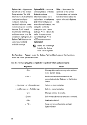
... all settings listed in Options computer, including List. Use the following keys to your option listed in the Options option selected in the Options Field are changeable. Appears on the the left side of your current down -arrow keys. As make features. or + Change existing item value. < Enter > Select the sub menu or execute command. < F9 > Load setup default. < F10 > Save current configuration and exit System Setup. 74 Options List - settings. Press < Enter> to display. - Key Functions...
... all settings listed in Options computer, including List. Use the following keys to your option listed in the Options option selected in the Options Field are changeable. Appears on the the left side of your current down -arrow keys. As make features. or + Change existing item value. < Enter > Select the sub menu or execute command. < F9 > Load setup default. < F10 > Save current configuration and exit System Setup. 74 Options List - settings. Press < Enter> to display. - Key Functions...
Owners Manual
Page 75
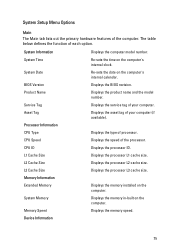
.... Device Information 75 System Setup Menu Options Main The Main tab lists out the primary hardware features of your computer (if available). System Information Displays the computer model number. Product Name Displays the product name and the model number. CPU ID Displays the processor ID. Memory Information Extended Memory Displays the memory installed on the computer's internal clock. Memory Speed Displays the memory speed. System Date Re-sets the date on the computer. Service Tag Displays...
.... Device Information 75 System Setup Menu Options Main The Main tab lists out the primary hardware features of your computer (if available). System Information Displays the computer model number. Product Name Displays the product name and the model number. CPU ID Displays the processor ID. Memory Information Extended Memory Displays the memory installed on the computer's internal clock. Memory Speed Displays the memory speed. System Date Re-sets the date on the computer. Service Tag Displays...

Owners Manual
Page 76
... be charged when connected to the on-board network card. Integrated NIC Enable or disable the power Default: Enabled supply to an AC power source. The table below defines the function of the function key . SATA Operation Change the SATA controller Default: AHCI mode to either ATA or AHCI. Adapter Warnings Enables or disables adapter Default: Enabled warnings. Virtualization Enable or disable the Intel Default: Enabled Virtualization feature. Default: Enabled 76 Displays the type of the hard drive. Fixed HDD AC Adapter Type Displays the model number and...
... be charged when connected to the on-board network card. Integrated NIC Enable or disable the power Default: Enabled supply to an AC power source. The table below defines the function of the function key . SATA Operation Change the SATA controller Default: AHCI mode to either ATA or AHCI. Adapter Warnings Enables or disables adapter Default: Enabled warnings. Virtualization Enable or disable the Intel Default: Enabled Virtualization feature. Default: Enabled 76 Displays the type of the hard drive. Fixed HDD AC Adapter Type Displays the model number and...

Owners Manual
Page 77
...'s internal hard drive (HDD). Diskette Drive Specify which the computer will boot through . 77 Set System Password Allows you to set password on -board devices like external USB ports, microphone, camera, media card reader, fingerprint reader, and boot disable (Default: Disabled). If the service tag is not already set, this field can boot through at start up. Boot The Boot tab allows you to manage the security features of different devices in which diskette drive the computer can be used to set , change, or delete the system password Set HDD Password...
...'s internal hard drive (HDD). Diskette Drive Specify which the computer will boot through . 77 Set System Password Allows you to set password on -board devices like external USB ports, microphone, camera, media card reader, fingerprint reader, and boot disable (Default: Disabled). If the service tag is not already set, this field can boot through at start up. Boot The Boot tab allows you to manage the security features of different devices in which diskette drive the computer can be used to set , change, or delete the system password Set HDD Password...

Owners Manual
Page 80
Standby Solid White On Solid White LED Front edge battery charge LED (Power Source: Battery; Battery Charge:
Standby Solid White On Solid White LED Front edge battery charge LED (Power Source: Battery; Battery Charge:

Owners Manual
Page 81
..., covers BIOS corruption or ROM error Code Cause Troubleshooting Steps 2 No RAM detected No memory detected Code 3 Cause Chipset Error (North and South Bridge Chipset, DMA/ IMR/ Timer Error) , Time-Of-Day Clock test failure , Gate A20 failure , Super I/O chip failure , Keyboard controller test failure Troubleshooting Steps System board Failure Code Cause Troubleshooting Steps 4 RAM Read/Write failure Memory failure Code Cause Troubleshooting Steps 5 Real-time clock power fail CMOS battery failure Code Cause Troubleshooting Steps 6 Video BIOS...
..., covers BIOS corruption or ROM error Code Cause Troubleshooting Steps 2 No RAM detected No memory detected Code 3 Cause Chipset Error (North and South Bridge Chipset, DMA/ IMR/ Timer Error) , Time-Of-Day Clock test failure , Gate A20 failure , Super I/O chip failure , Keyboard controller test failure Troubleshooting Steps System board Failure Code Cause Troubleshooting Steps 4 RAM Read/Write failure Memory failure Code Cause Troubleshooting Steps 5 Real-time clock power fail CMOS battery failure Code Cause Troubleshooting Steps 6 Video BIOS...

Owners Manual
Page 84
...: Internal External Speakers Internal speaker amplifier Volume controls Communications Network adapter Wireless Ports and Connectors Audio Video Network adapter USB Memory card reader Display Type 84 Conexant CX20671 24-bit (analog-to-digital and digital-toanalog) high definition audio microphone-in/stereo headphones combo connector two (2W) two (2W) Software program menus, media controls, and keyboard function keys 10/100/1000 Mbps Ethernet LAN internal wireless local area network (WLAN), Bluetooth, Mobile Broadband, and 4G Mobile Broadband wireless support Audio in / one out combo jack one...
...: Internal External Speakers Internal speaker amplifier Volume controls Communications Network adapter Wireless Ports and Connectors Audio Video Network adapter USB Memory card reader Display Type 84 Conexant CX20671 24-bit (analog-to-digital and digital-toanalog) high definition audio microphone-in/stereo headphones combo connector two (2W) two (2W) Software program menus, media controls, and keyboard function keys 10/100/1000 Mbps Ethernet LAN internal wireless local area network (WLAN), Bluetooth, Mobile Broadband, and 4G Mobile Broadband wireless support Audio in / one out combo jack one...


