Vostro 14 5415 Setup and Specifications
Page 3
... location...10 Battery Charge and Status LED ...11 Chapter 3: Specifications of Vostro 14 5415 12 Dimensions and weight...12 Processor...13 Chipset...13 Operating system...13 Memory...13 External ports...14 Internal slots...14 Ethernet...15 Wireless module...15 Audio...15 Storage...16 Media-card reader...16 Keyboard...16 Camera...17 Touchpad...17 Power adapter...18 Battery...18 Display...19 Fingerprint reader (optional)...20 GPU-Integrated...20 Computer environment...20 Chapter 4: Keyboard shortcuts...22 Chapter 5: Getting help and contacting Dell...
... location...10 Battery Charge and Status LED ...11 Chapter 3: Specifications of Vostro 14 5415 12 Dimensions and weight...12 Processor...13 Chipset...13 Operating system...13 Memory...13 External ports...14 Internal slots...14 Ethernet...15 Wireless module...15 Audio...15 Storage...16 Media-card reader...16 Keyboard...16 Camera...17 Touchpad...17 Power adapter...18 Battery...18 Display...19 Fingerprint reader (optional)...20 GPU-Integrated...20 Computer environment...20 Chapter 4: Keyboard shortcuts...22 Chapter 5: Getting help and contacting Dell...
Vostro 14 5415 Setup and Specifications
Page 4
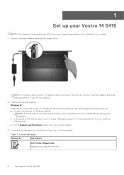
... create a Microsoft account. Finish operating system setup. Locate and use Dell apps from your computer depending on the computer. 2. Table 1. NOTE: If connecting to a secured wireless network, enter the password for Windows updates. NOTE: To conserve battery power, the battery might enter power-saving mode. When setting up, Dell Technologies recommends that you ordered. 1. Connect the power adapter and press the power button. Windows 10: Follow the on-screen instructions to turn on the configuration you : ● Connect to a network for the wireless network access...
... create a Microsoft account. Finish operating system setup. Locate and use Dell apps from your computer depending on the computer. 2. Table 1. NOTE: If connecting to a secured wireless network, enter the password for Windows updates. NOTE: To conserve battery power, the battery might enter power-saving mode. When setting up, Dell Technologies recommends that you ordered. 1. Connect the power adapter and press the power button. Windows 10: Follow the on-screen instructions to turn on the configuration you : ● Connect to a network for the wireless network access...
Vostro 14 5415 Setup and Specifications
Page 7
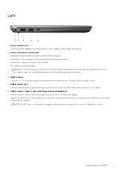
... as external storage devices, printers, and external displays. Power-adapter port Connect a power adapter to provide power to 15 W power output that enables two-way power supply between devices. Power and battery-status light Indicates the power state and battery state of Vostro 14 5415 7 USB 3.2 Gen 1 (Type-C) port with Power Delivery/DisplayPort Connect devices such as external storage devices and printers. Off-Battery is low or critical. Solid amber-Battery charge is fully charged. NOTE: On certain computer models, the power and battery-status light are also used for...
... as external storage devices, printers, and external displays. Power-adapter port Connect a power adapter to provide power to 15 W power output that enables two-way power supply between devices. Power and battery-status light Indicates the power state and battery state of Vostro 14 5415 7 USB 3.2 Gen 1 (Type-C) port with Power Delivery/DisplayPort Connect devices such as external storage devices and printers. Off-Battery is low or critical. Solid amber-Battery charge is fully charged. NOTE: On certain computer models, the power and battery-status light are also used for...

Vostro 14 5415 Setup and Specifications
Page 12
... in.) Weight NOTE: The weight of Vostro 14 5415 Table 3. maximum 12 Specifications of your Vostro 14 5415. 3 Specifications of Vostro 14 5415 Topics: • Dimensions and weight • Processor • Chipset • Operating system • Memory • External ports • Internal slots • Ethernet • Wireless module • Audio • Storage • Media-card reader • Keyboard • Camera • Touchpad • Power adapter • Battery • Display • Fingerprint reader (optional) • GPU-Integrated • Computer environment...
... in.) Weight NOTE: The weight of Vostro 14 5415 Table 3. maximum 12 Specifications of your Vostro 14 5415. 3 Specifications of Vostro 14 5415 Topics: • Dimensions and weight • Processor • Chipset • Operating system • Memory • External ports • Internal slots • Ethernet • Wireless module • Audio • Storage • Media-card reader • Keyboard • Camera • Touchpad • Power adapter • Battery • Display • Fingerprint reader (optional) • GPU-Integrated • Computer environment...

Vostro 14 5415 Setup and Specifications
Page 14
Table 7. External ports Description Network port Values One RJ45 Ethernet port USB ports ● Two USB 3.2 Gen 1 ports ● One USB 3.2 Gen 1 Type-C with Power Delivery/ DisplayPort Alt Mode Audio port One Global headset jack Video port ● HDMI 1.4 port ● USB 3.2 Gen 1 Type-C with DisplayPort alt Mode Media-card reader micro-SD Card reader Power-adapter port One 4.5 mm x 2.9 mm DC-in port Security-cable slot One Wedge-shaped lock slot Internal slots The following table lists the external ports of Vostro 14 5415 Table 8. Internal slots Description M.2...
Table 7. External ports Description Network port Values One RJ45 Ethernet port USB ports ● Two USB 3.2 Gen 1 ports ● One USB 3.2 Gen 1 Type-C with Power Delivery/ DisplayPort Alt Mode Audio port One Global headset jack Video port ● HDMI 1.4 port ● USB 3.2 Gen 1 Type-C with DisplayPort alt Mode Media-card reader micro-SD Card reader Power-adapter port One 4.5 mm x 2.9 mm DC-in port Security-cable slot One Wedge-shaped lock slot Internal slots The following table lists the external ports of Vostro 14 5415 Table 8. Internal slots Description M.2...

Vostro 14 5415 Setup and Specifications
Page 22
... the keyboard are needed for specific software applications, multi-media functionality can also define the primary behavior of keyboard shortcuts Function key Re-defined key (for shortcuts remain the same across all language configurations. Keys used with selected keys on the upper part of keyboard shortcuts Function key Behavior fn + B Pause/Break fn + Insert Sleep fn + H Toggle between power light and battery-status light fn + S Toggle scroll lock fn + R System request fn + ctrl Open application menu fn...
... the keyboard are needed for specific software applications, multi-media functionality can also define the primary behavior of keyboard shortcuts Function key Re-defined key (for shortcuts remain the same across all language configurations. Keys used with selected keys on the upper part of keyboard shortcuts Function key Behavior fn + B Pause/Break fn + Insert Sleep fn + H Toggle between power light and battery-status light fn + S Toggle scroll lock fn + R System request fn + ctrl Open application menu fn...

Vostro 14 5415 Service Manual
Page 4
... Entering BIOS setup program...61 Navigation keys...61 Boot Sequence...62 System setup options...62 System and admin password...67 Assigning a system setup password...67 Deleting or changing an existing system setup password 68 Clearing BIOS (System Setup) and System passwords 68 Chapter 5: Troubleshooting...69 Dell SupportAssist Pre-boot System Performance Check diagnostics 69 Running the SupportAssist Pre-Boot System Performance Check 69 System diagnostic lights...70 Recovering the operating system...71 Flashing BIOS (USB key)...71 Flashing the BIOS...
... Entering BIOS setup program...61 Navigation keys...61 Boot Sequence...62 System setup options...62 System and admin password...67 Assigning a system setup password...67 Deleting or changing an existing system setup password 68 Clearing BIOS (System Setup) and System passwords 68 Chapter 5: Troubleshooting...69 Dell SupportAssist Pre-boot System Performance Check diagnostics 69 Running the SupportAssist Pre-Boot System Performance Check 69 System diagnostic lights...70 Recovering the operating system...71 Flashing BIOS (USB key)...71 Flashing the BIOS...

Vostro 14 5415 Service Manual
Page 6
..., replace all covers, panels, and screws before opening the computer cover or panels. Disconnect your operating system for shut-down instructions. 3. Click Start > Power > Shut down your computer from all attached devices from their edges, and avoid touching the pins and the contacts. 6 Working inside your computer, read the safety information that shipped with your computer and then unplug the cable from the network device. 5. NOTE...
..., replace all covers, panels, and screws before opening the computer cover or panels. Disconnect your operating system for shut-down instructions. 3. Click Start > Power > Shut down your computer from all attached devices from their edges, and avoid touching the pins and the contacts. 6 Working inside your computer, read the safety information that shipped with your computer and then unplug the cable from the network device. 5. NOTE...
Vostro 14 5415 Service Manual
Page 7
... and eject any installed card from its pull tab, not the cable itself. NOTE: Tests for wireless device employs a unit of the U.S. The more difficult type of the time when damage occurs, it by your computer 7 The use anti-static floor pads and workbench pads. ● When unpacking a static-sensitive component from the media-card reader. they do not remove the component from...
... and eject any installed card from its pull tab, not the cable itself. NOTE: Tests for wireless device employs a unit of the U.S. The more difficult type of the time when damage occurs, it by your computer 7 The use anti-static floor pads and workbench pads. ● When unpacking a static-sensitive component from the media-card reader. they do not remove the component from...

Vostro 14 5415 Service Manual
Page 9
.... Replace any media cards, discs, or any external devices, peripherals, or cables you removed before working inside your computer About this task CAUTION: Leaving stray or loose screws inside your toes out. 2. Transporting sensitive components When transporting ESD sensitive components such as replacement parts or parts to be returned to Dell, it is to their electrical outlets. 5. Always obtain additional resources or use a mechanical...
.... Replace any media cards, discs, or any external devices, peripherals, or cables you removed before working inside your computer About this task CAUTION: Leaving stray or loose screws inside your toes out. 2. Transporting sensitive components When transporting ESD sensitive components such as replacement parts or parts to be returned to Dell, it is to their electrical outlets. 5. Always obtain additional resources or use a mechanical...

Vostro 14 5415 Service Manual
Page 21
Using your fingertips, carefully spread apart the securing-clips on the system board. NOTE: Your computer may have up . 3. Steps 1. Repeat steps 1 to access the memory module. 2. Installing the memory Prerequisites If you are replacing a component, remove the existing component before performing the installation process. About this task The following image(s) indicate the location of the memory and provides a visual representation of the memory-module slot until the...
Using your fingertips, carefully spread apart the securing-clips on the system board. NOTE: Your computer may have up . 3. Steps 1. Repeat steps 1 to access the memory module. 2. Installing the memory Prerequisites If you are replacing a component, remove the existing component before performing the installation process. About this task The following image(s) indicate the location of the memory and provides a visual representation of the memory-module slot until the...

Vostro 14 5415 Service Manual
Page 59
Install the touchpad. 6. Install the power-adapter port. 9. Install the M.2 2280 solid-state drive. 11. Install the coin-cell battery. 13. Removing and installing components 59 Install the display assembly. 4. Install the I/O board. 8. Install the wireless card. 10. Steps Place the palm-rest and keyboard assembly on a flat and clean surface and perform the post-requisites to install the palm-rest and keyboard assembly. Install the base cover. 15. Follow the procedure in After working inside...
Install the touchpad. 6. Install the power-adapter port. 9. Install the M.2 2280 solid-state drive. 11. Install the coin-cell battery. 13. Removing and installing components 59 Install the display assembly. 4. Install the I/O board. 8. Install the wireless card. 10. Steps Place the palm-rest and keyboard assembly on a flat and clean surface and perform the post-requisites to install the palm-rest and keyboard assembly. Install the base cover. 15. Follow the procedure in After working inside...
Vostro 14 5415 Service Manual
Page 61
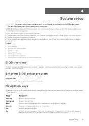
... keys • Boot Sequence • System setup options • System and admin password • Clearing BIOS (System Setup) and System passwords BIOS overview The BIOS manages data flow between the computer's operating system and attached devices such as the user password, type of hard drive installed, and enabling or disabling base devices. Selects a value in the selected field (if applicable) or follow the link in the main screen displays a message that you make your computer work incorrectly...
... keys • Boot Sequence • System setup options • System and admin password • Clearing BIOS (System Setup) and System passwords BIOS overview The BIOS manages data flow between the computer's operating system and attached devices such as the user password, type of hard drive installed, and enabling or disabling base devices. Selects a value in the selected field (if applicable) or follow the link in the main screen displays a message that you make your computer work incorrectly...

Vostro 14 5415 Service Manual
Page 62
... CPU Type CPU Speed CPU ID CPU Cache L1 Cache L2 Cache L3 Cache M.2 PCIe SSD AC Adapter Type System Memory Memory Speed Keyboard Type Displays the BIOS version of the computer. Displays whether an AC adapter is installed. Displays the total computer memory installed. Displays the memory speed. Options are : UEFI only: ● Windows Boot Manager ● UEFI RST KXG60ZNV512G NVMe KIOXIA 512 GB 40NA83SKJ81L The boot sequence screen also displays the option to access the System Setup screen. System setup options-Main menu...
... CPU Type CPU Speed CPU ID CPU Cache L1 Cache L2 Cache L3 Cache M.2 PCIe SSD AC Adapter Type System Memory Memory Speed Keyboard Type Displays the BIOS version of the computer. Displays whether an AC adapter is installed. Displays the total computer memory installed. Displays the memory speed. Options are : UEFI only: ● Windows Boot Manager ● UEFI RST KXG60ZNV512G NVMe KIOXIA 512 GB 40NA83SKJ81L The boot sequence screen also displays the option to access the System Setup screen. System setup options-Main menu...

Vostro 14 5415 Service Manual
Page 65
... setup options-Advance menu (continued) Advance ● Disabled (Default) ● Enabled SupportAssist System Resolution Onboard Diagnostics Auto OS Recovery Threshold Performs SupportAssist OS recovery after the set the System Password. Asset Tag Admin Password System Password Displays and allows to skip BIOS PPI user prompts when issuing TPM PPI enable and activate commands. Set, change , or delete the computer password. The options are : ● Activate ● Deactivate Displays the Status of the Absolute Module...
... setup options-Advance menu (continued) Advance ● Disabled (Default) ● Enabled SupportAssist System Resolution Onboard Diagnostics Auto OS Recovery Threshold Performs SupportAssist OS recovery after the set the System Password. Asset Tag Admin Password System Password Displays and allows to skip BIOS PPI user prompts when issuing TPM PPI enable and activate commands. Set, change , or delete the computer password. The options are : ● Activate ● Deactivate Displays the Status of the Absolute Module...

Vostro 14 5415 Service Manual
Page 66
... validated boot software. The options are : ● Disabled ● Enabled (Default) Enable or disable BIOS updates through UEFI capsule update packages. System setup options-Security menu Security Attestation Enable Key Storage Enable SHA-256 Clear PPI Bypass for Clear Commands TPM Status UEFI Firmware Capsule Updates ● Disabled (Default) ● Enabled Provides for the user to control whether TPM Storage Hierarchy is available to skip BIOS PPI user prompts when issuing the Clear command. File Browser Del Boot Option Windows Boot Manager: Displays the Dell Boot Path...
... validated boot software. The options are : ● Disabled ● Enabled (Default) Enable or disable BIOS updates through UEFI capsule update packages. System setup options-Security menu Security Attestation Enable Key Storage Enable SHA-256 Clear PPI Bypass for Clear Commands TPM Status UEFI Firmware Capsule Updates ● Disabled (Default) ● Enabled Provides for the user to control whether TPM Storage Hierarchy is available to skip BIOS PPI user prompts when issuing the Clear command. File Browser Del Boot Option Windows Boot Manager: Displays the Dell Boot Path...

Vostro 14 5415 Service Manual
Page 68
... Dell Tech Support number in your computer's service tag number into the locked BIOS/system setup screen. 2. If you to save the changes and exit from System Setup. Clearing BIOS (System Setup) and System passwords About this task To enter the System Setup, press F2 immediately after a power-on or reboot. You cannot delete or change the System and/or Setup password, re enter the new password when prompted. Steps 1. In the System BIOS or System Setup screen...
... Dell Tech Support number in your computer's service tag number into the locked BIOS/system setup screen. 2. If you to save the changes and exit from System Setup. Clearing BIOS (System Setup) and System passwords About this task To enter the System Setup, press F2 immediately after a power-on or reboot. You cannot delete or change the System and/or Setup password, re enter the new password when prompted. Steps 1. In the System BIOS or System Setup screen...

Vostro 14 5415 Service Manual
Page 70
... problem persists, replace the RTC battery. BIOS recovery image found Flash latest BIOS version. If problem persists, replace the memory module. LCD failure (SBIOS message) Replace the LCD module. PCI or Video card/chip failure Replace the system board. Solid white - Power adapter is running on battery and the battery has less than 5 percent charge. The power and battery-status light blinks amber along with beep codes indicating failures. This 2,3 pattern continues until the computer is turned off . Invalid memory installed Reset and swap memory modules...
... problem persists, replace the RTC battery. BIOS recovery image found Flash latest BIOS version. If problem persists, replace the memory module. LCD failure (SBIOS message) Replace the LCD module. PCI or Video card/chip failure Replace the system board. Solid white - Power adapter is running on battery and the battery has less than 5 percent charge. The power and battery-status light blinks amber along with beep codes indicating failures. This 2,3 pattern continues until the computer is turned off . Invalid memory installed Reset and swap memory modules...
Vostro 14 5415 Service Manual
Page 71
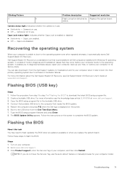
... all Dell computers installed with Windows 10 operating system. Connect the bootable USB drive to step 7 in use . ● Off - Type the BIOS setup program filename and press Enter. 8. The BIOS Update Utility appears. Go to complete the BIOS update. Create a bootable USB drive. Camera is unable to boot to download the latest BIOS setup program file. 2. For more information about the Dell SupportAssist OS Recovery, see the knowledge base article SLN143196 at www.dell.com/support. Follow the instructions...
... all Dell computers installed with Windows 10 operating system. Connect the bootable USB drive to step 7 in use . ● Off - Type the BIOS setup program filename and press Enter. 8. The BIOS Update Utility appears. Go to complete the BIOS update. Create a bootable USB drive. Camera is unable to boot to download the latest BIOS setup program file. 2. For more information about the Dell SupportAssist OS Recovery, see the knowledge base article SLN143196 at www.dell.com/support. Follow the instructions...
Vostro 14 5415 Service Manual
Page 72
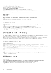
... screen will display multiple color bars and change colors on the laptop to red, green, and blue. 6. Press Esc key to invoke LCD BIST Test 1. The following procedure provides the instructions on the screen. Click Download to WiFi connectivity issues a WiFi power cycle procedure may exhibit two states: a. NOTE: M-BIST can be initiated on the LCD (screen). 5. AMBER: Indicates a problem with the video card (GPU) and PC settings. Scroll down , the battery indicator LED...
... screen will display multiple color bars and change colors on the laptop to red, green, and blue. 6. Press Esc key to invoke LCD BIST Test 1. The following procedure provides the instructions on the screen. Click Download to WiFi connectivity issues a WiFi power cycle procedure may exhibit two states: a. NOTE: M-BIST can be initiated on the LCD (screen). 5. AMBER: Indicates a problem with the video card (GPU) and PC settings. Scroll down , the battery indicator LED...


