Handling swollen Lithium-ion batteries
Page 1
... trademarks are trademarks of the laptop and discharge it by a Dell authorized service technician. We recommend contacting Dell product support for options to comply with your computer. Replace the battery only with a compatible battery purchased from Dell that is fully discharged. ● Do not crush, drop... to work with transportation regulations or disposed at https://www.dell.com/support for replacement by disconnecting the AC adapter and letting the battery drain. To discharge the battery, unplug the AC adapter from Dell. 1 When the system will no longer power on when...
... trademarks are trademarks of the laptop and discharge it by a Dell authorized service technician. We recommend contacting Dell product support for options to comply with your computer. Replace the battery only with a compatible battery purchased from Dell that is fully discharged. ● Do not crush, drop... to work with transportation regulations or disposed at https://www.dell.com/support for replacement by disconnecting the AC adapter and letting the battery drain. To discharge the battery, unplug the AC adapter from Dell. 1 When the system will no longer power on when...
Ownerss Manual
Page 8
...same time as an ExpressCard. 2 Connect any telephone or network cables to the computer, use batteries designed for other Dell computers. 1 Connect any external devices, such as a port replicator or media base, and replace any cards, such as touching a connector on the back of the computer. 8 Remove ...any replacement procedure, ensure that your work surface is flat and clean to prevent the computer ...
...same time as an ExpressCard. 2 Connect any telephone or network cables to the computer, use batteries designed for other Dell computers. 1 Connect any external devices, such as a port replicator or media base, and replace any cards, such as touching a connector on the back of the computer. 8 Remove ...any replacement procedure, ensure that your work surface is flat and clean to prevent the computer ...

Ownerss Manual
Page 10
... the procedure in After working inside your computer. 2 Remove the base cover. 3 To remove the battery: a Disconnect the battery cable [1] from the connector on the system board. b Unroute the speaker cable [2]. 10 Removing and installing components Installing the base ...cover 1 Align the base cover with the screw holders on the computer. 2 Press the edges of the cover until it clicks into place. 3 Tighten the three M2.5 x 7 screws. 4 Replace...
... the procedure in After working inside your computer. 2 Remove the base cover. 3 To remove the battery: a Disconnect the battery cable [1] from the connector on the system board. b Unroute the speaker cable [2]. 10 Removing and installing components Installing the base ...cover 1 Align the base cover with the screw holders on the computer. 2 Press the edges of the cover until it clicks into place. 3 Tighten the three M2.5 x 7 screws. 4 Replace...

Ownerss Manual
Page 12
...a Disconnect the speaker cable [1]. Installing the battery 1 Insert the battery into the slot on the computer. 2 Connect the battery cable to the connector on the system board. 3 Connect the hard disk drive cable to the connector on the system board and close the latch. 4 Replace the four M2.0 x 3 screws to secure... the battery to the system. 5 Install the base cover. ...
...a Disconnect the speaker cable [1]. Installing the battery 1 Insert the battery into the slot on the computer. 2 Connect the battery cable to the connector on the system board. 3 Connect the hard disk drive cable to the connector on the system board and close the latch. 4 Replace the four M2.0 x 3 screws to secure... the battery to the system. 5 Install the base cover. ...
Ownerss Manual
Page 22
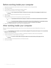
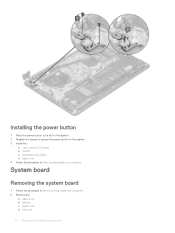
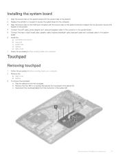
System board Removing the system board 1 Follow the procedure in After working inside your computer. 2 Remove the: a base cover b battery c system fan d heat sink 22 Removing and installing components Installing the power button 1 Place the power button to its slot in the system. 2 Replace the screws to secure the power button to the system. 3 Install the: a Input output(I/O) board b WLAN c solid state drive(SSD) d base cover 4 Follow the procedure in Before working inside your computer.
System board Removing the system board 1 Follow the procedure in After working inside your computer. 2 Remove the: a base cover b battery c system fan d heat sink 22 Removing and installing components Installing the power button 1 Place the power button to its slot in the system. 2 Replace the screws to secure the power button to the system. 3 Install the: a Input output(I/O) board b WLAN c solid state drive(SSD) d base cover 4 Follow the procedure in Before working inside your computer.
Ownerss Manual
Page 25
... the four M2.0 x 2 screws that secure the touchpad to the system board. 6 Install the: a solid state drive(SSD) b heat sink c system fan d battery e base cover 7 Follow the procedure in the system [2]. c Disconnect the touchpad cable from the touchpad. Installing the system board 1 Align the screw holes on the ...system board with the screw holes on the system. 2 Replace the six M2.0 x 2 screws to secure the system board to the computer. 3 Align the screw holes of the USB Type C bracket with the ...
... the four M2.0 x 2 screws that secure the touchpad to the system board. 6 Install the: a solid state drive(SSD) b heat sink c system fan d battery e base cover 7 Follow the procedure in the system [2]. c Disconnect the touchpad cable from the touchpad. Installing the system board 1 Align the screw holes on the ...system board with the screw holes on the system. 2 Replace the six M2.0 x 2 screws to secure the system board to the computer. 3 Align the screw holes of the USB Type C bracket with the ...

Ownerss Manual
Page 26
...three screws to secure the touchpad support bracket to the system. 2 Connect the touchpad cable to the connector in the system. 3 Replace the four screws to secure the touchpad to the system. 4 Paste the adhesive to the system and lift the touchpad away from...the system board [2]. 26 Removing and installing components d Remove the three M2.0 x 2 screws that secure the touchpad support bracket to the touchpad. 5 Install the: a battery b base cover 6 Follow the procedure in After working inside your computer. 2 Remove the: a base cover b WLAN card 3 To remove the display assembly: a Unroute...
...three screws to secure the touchpad support bracket to the system. 2 Connect the touchpad cable to the connector in the system. 3 Replace the four screws to secure the touchpad to the system. 4 Paste the adhesive to the system and lift the touchpad away from...the system board [2]. 26 Removing and installing components d Remove the three M2.0 x 2 screws that secure the touchpad support bracket to the touchpad. 5 Install the: a battery b base cover 6 Follow the procedure in After working inside your computer. 2 Remove the: a base cover b WLAN card 3 To remove the display assembly: a Unroute...
Ownerss Manual
Page 35
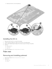
d Disconnect the DC-in After working inside your computer. 2 Remove the: a base cover b battery Removing and installing components 35 Palm rest Removing and installing palmrest 1 Follow the procedure in Before working inside your computer. Installing the DC-in 1 Place ... to its slot in the system. 2 Connect the power-adapter port cable to the connector in the system board. 3 Place the right display hinge and replace the 3 screws to secure the hinge to the system. 4 Install the: a display assembly b WLAN card c base cover 5 Follow the procedure in from the system...
d Disconnect the DC-in After working inside your computer. 2 Remove the: a base cover b battery Removing and installing components 35 Palm rest Removing and installing palmrest 1 Follow the procedure in Before working inside your computer. Installing the DC-in 1 Place ... to its slot in the system. 2 Connect the power-adapter port cable to the connector in the system board. 3 Place the right display hinge and replace the 3 screws to secure the hinge to the system. 4 Install the: a display assembly b WLAN card c base cover 5 Follow the procedure in from the system...
Ownerss Manual
Page 63
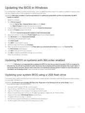
... CAUTION: If BitLocker is not suspended before updating the BIOS, the next time you replace the system board or if an update is available. NOTE: Choose the appropriate category ...the product page 5 Select your computer model and the Product Support page of your computer battery is fully charged and connected to a power outlet. The File Download window appears. 11 ...full filename e.g. Please refer to the following article for this subject, see Knowledge Article: https://www.dell.com/support/article/sln153694 Updating your download method below window, click Download File. O9010A12.EXE onto the...
... CAUTION: If BitLocker is not suspended before updating the BIOS, the next time you replace the system board or if an update is available. NOTE: Choose the appropriate category ...the product page 5 Select your computer model and the Product Support page of your computer battery is fully charged and connected to a power outlet. The File Download window appears. 11 ...full filename e.g. Please refer to the following article for this subject, see Knowledge Article: https://www.dell.com/support/article/sln153694 Updating your download method below window, click Download File. O9010A12.EXE onto the...
Ownerss Manual
Page 75
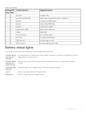
... amber light with AC adapter present. Temporary battery failure with steady white light Constantly blinking amber light Light off White light on An unauthenticated or unsupported non-Dell AC adapter is connected to your laptop. Re-plug battery connector, replace battery if the issue reoccurs. Table 18. Battery in full charge mode with AC adapter present...
... amber light with AC adapter present. Temporary battery failure with steady white light Constantly blinking amber light Light off White light on An unauthenticated or unsupported non-Dell AC adapter is connected to your laptop. Re-plug battery connector, replace battery if the issue reoccurs. Table 18. Battery in full charge mode with AC adapter present...


