Handling swollen Lithium-ion batteries
Page 1
... recent years and have become standard in an approved shipping container (provided by Dell), to lithium-ion polymer battery technology is the lithium-ion polymer battery. Dell, EMC, and other computers with newer ultra-thin laptops) and long battery life. To discharge the battery, unplug the AC adapter from other trademarks are trademarks of the applicable...
... recent years and have become standard in an approved shipping container (provided by Dell), to lithium-ion polymer battery technology is the lithium-ion polymer battery. Dell, EMC, and other computers with newer ultra-thin laptops) and long battery life. To discharge the battery, unplug the AC adapter from other trademarks are trademarks of the applicable...

Handling swollen Lithium-ion batteries
Page 2
Lithium-ion batteries can swell for various reasons such as age, number of charge cycles, or exposure to minimize the possibility of occurrence of the laptop battery and to high heat. Frequently Asked Questions. 2 For more information on how to improve the performance and lifespan of the issue, see Dell Laptop Battery -
Lithium-ion batteries can swell for various reasons such as age, number of charge cycles, or exposure to minimize the possibility of occurrence of the laptop battery and to high heat. Frequently Asked Questions. 2 For more information on how to improve the performance and lifespan of the issue, see Dell Laptop Battery -
Quick Start Guide
Page 2
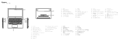
Features 1. 摄像头 2 3 4. Camera 2. microSD card reader 9. Power and battery‑status light 14. Speakers 16. Service tag label 1. 攝影機 2 3 4. USB 3.1 Gen 1(Type-C)ポート (Power Delivery/DisplayPort 13 ...
Features 1. 摄像头 2 3 4. Camera 2. microSD card reader 9. Power and battery‑status light 14. Speakers 16. Service tag label 1. 攝影機 2 3 4. USB 3.1 Gen 1(Type-C)ポート (Power Delivery/DisplayPort 13 ...

Ownerss Manual
Page 3
......9 Base cover...9 Removing the base cover...9 Installing the base cover...10 Battery...10 Removing the battery...10 Installing the battery...12 Speaker...12 Removing the speaker...12 Installing the speaker...13 Coin-cell battery...13 Removing the coin cell battery...13 Installing the coin cell battery...14 Solid State Drive ...14 Removing the M.2 Solid-State Drive...
......9 Base cover...9 Removing the base cover...9 Installing the base cover...10 Battery...10 Removing the battery...10 Installing the battery...12 Speaker...12 Removing the speaker...12 Installing the speaker...13 Coin-cell battery...13 Removing the coin cell battery...13 Installing the coin cell battery...14 Solid State Drive ...14 Removing the M.2 Solid-State Drive...

Ownerss Manual
Page 5
... Communication specification...47 Ports and connectors specification...47 Display specification...47 Keyboard...48 Touchpad specification...48 Camera...48 Storage specification...48 Battery specification...48 AC adapter...49 Physical specification...50 Environmental specification...50 5 System setup...51 Boot menu...51 Navigation keys...51 ... ...63 Updating BIOS on systems with BitLocker enabled 63 Updating your system BIOS using a USB flash drive 63 Updating the Dell BIOS in Linux and Ubuntu environments 64 Flashing the BIOS from the F12 One-Time boot menu 64 System and setup password...
... Communication specification...47 Ports and connectors specification...47 Display specification...47 Keyboard...48 Touchpad specification...48 Camera...48 Storage specification...48 Battery specification...48 AC adapter...49 Physical specification...50 Environmental specification...50 5 System setup...51 Boot menu...51 Navigation keys...51 ... ...63 Updating BIOS on systems with BitLocker enabled 63 Updating your system BIOS using a USB flash drive 63 Updating the Dell BIOS in Linux and Ubuntu environments 64 Flashing the BIOS from the F12 One-Time boot menu 64 System and setup password...

Ownerss Manual
Page 6
Downloading drivers...69 Chipset drivers...69 Graphics controller driver...70 USB drivers...71 Network drivers...71 Audio drivers...71 Storage controller drivers...71 Other drivers...72 Security device drivers...72 Software device drivers...72 Human Interface Device drivers...72 Firmware...72 Intel Dynamic Platform and Thermal Framework 73 7 Troubleshooting...74 Dell Enhanced Pre-Boot System Assessment - ePSA Diagnostic 3.0 74 Running the ePSA Diagnostics...74 Diagnostic LED...74 Battery status lights...75 8 Contacting Dell...76 6 Contents
Downloading drivers...69 Chipset drivers...69 Graphics controller driver...70 USB drivers...71 Network drivers...71 Audio drivers...71 Storage controller drivers...71 Other drivers...72 Security device drivers...72 Software device drivers...72 Human Interface Device drivers...72 Firmware...72 Intel Dynamic Platform and Thermal Framework 73 7 Troubleshooting...74 Dell Enhanced Pre-Boot System Assessment - ePSA Diagnostic 3.0 74 Running the ePSA Diagnostics...74 Diagnostic LED...74 Battery status lights...75 8 Contacting Dell...76 6 Contents
Ownerss Manual
Page 8
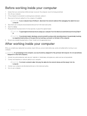
CAUTION: To avoid damage to the computer, use batteries designed for this particular Dell computer. Do not use only the battery designed for other Dell computers. 1 Connect any external devices, such as a port replicator or media base, and replace any cards, such as touching a connector on your computer. CAUTION: To ...
CAUTION: To avoid damage to the computer, use batteries designed for this particular Dell computer. Do not use only the battery designed for other Dell computers. 1 Connect any external devices, such as a port replicator or media base, and replace any cards, such as touching a connector on your computer. CAUTION: To ...

Ownerss Manual
Page 10
... screw holders on the system board. b Unroute the speaker cable [2]. 10 Removing and installing components Battery Removing the battery 1 Follow the procedure in After working inside your computer. 2 Remove the base cover. 3 To remove the battery: a Disconnect the battery cable [1] from the connector on the computer. 2 Press the edges of the cover until it...
... screw holders on the system board. b Unroute the speaker cable [2]. 10 Removing and installing components Battery Removing the battery 1 Follow the procedure in After working inside your computer. 2 Remove the base cover. 3 To remove the battery: a Disconnect the battery cable [1] from the connector on the computer. 2 Press the edges of the cover until it...

Ownerss Manual
Page 11
d Lift the battery away from the system [2]. c Remove the four M2.0 x 3 screws [1]. Removing and installing components 11
d Lift the battery away from the system [2]. c Remove the four M2.0 x 3 screws [1]. Removing and installing components 11

Ownerss Manual
Page 12
... the speaker cable, and remove it away from the back cover. 12 Removing and installing components Installing the battery 1 Insert the battery into the slot on the computer. 2 Connect the battery cable to the connector on the system board. 3 Connect the hard disk drive cable to the connector on... the system board and close the latch. 4 Replace the four M2.0 x 3 screws to secure the battery to the system. 5 Install the base cover. 6 Follow the procedure in Before working inside your computer. Speaker Removing the speaker 1 Follow the procedure in...
... the speaker cable, and remove it away from the back cover. 12 Removing and installing components Installing the battery 1 Insert the battery into the slot on the computer. 2 Connect the battery cable to the connector on the system board. 3 Connect the hard disk drive cable to the connector on... the system board and close the latch. 4 Replace the four M2.0 x 3 screws to secure the battery to the system. 5 Install the base cover. 6 Follow the procedure in Before working inside your computer. Speaker Removing the speaker 1 Follow the procedure in...

Ownerss Manual
Page 13
... procedure in After working inside your computer. 2 Remove the base cover. 3 To remove the coin cell battery: a Disconnect the coin cell battery cable from the system board [2]. b Pry the coin cell battery to the system board. 4 Install the: a battery b base cover 5 Follow the procedure in Before working inside your computer. Installing the speaker 1 Align...
... procedure in After working inside your computer. 2 Remove the base cover. 3 To remove the coin cell battery: a Disconnect the coin cell battery cable from the system board [2]. b Pry the coin cell battery to the system board. 4 Install the: a battery b base cover 5 Follow the procedure in Before working inside your computer. Installing the speaker 1 Align...

Ownerss Manual
Page 14
... the SSD away from the system [2]. 14 Removing and installing components Solid State Drive Removing the M.2 Solid-State Drive - Installing the coin cell battery 1 Place the coin cell battery into the slot on the system board. 3 Install the base cover. 4 Follow the procedure in Before working inside your computer. SSD 1 Follow the... remove the solid-state drive (SSD): a Remove the M2.0 x 3 screw that secure the SSD to the connector on the system board. 2 Connect the coin cell battery cable to the system [1].
... the SSD away from the system [2]. 14 Removing and installing components Solid State Drive Removing the M.2 Solid-State Drive - Installing the coin cell battery 1 Place the coin cell battery into the slot on the system board. 3 Install the base cover. 4 Follow the procedure in Before working inside your computer. SSD 1 Follow the... remove the solid-state drive (SSD): a Remove the M2.0 x 3 screw that secure the SSD to the connector on the system board. 2 Connect the coin cell battery cable to the system [1].
Ownerss Manual
Page 22
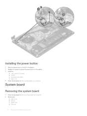
System board Removing the system board 1 Follow the procedure in After working inside your computer. 2 Remove the: a base cover b battery c system fan d heat sink 22 Removing and installing components Installing the power button 1 Place the power button to its slot in the system. 2 Replace the screws to secure the power button to the system. 3 Install the: a Input output(I/O) board b WLAN c solid state drive(SSD) d base cover 4 Follow the procedure in Before working inside your computer.
System board Removing the system board 1 Follow the procedure in After working inside your computer. 2 Remove the: a base cover b battery c system fan d heat sink 22 Removing and installing components Installing the power button 1 Place the power button to its slot in the system. 2 Replace the screws to secure the power button to the system. 3 Install the: a Input output(I/O) board b WLAN c solid state drive(SSD) d base cover 4 Follow the procedure in Before working inside your computer.
Ownerss Manual
Page 25
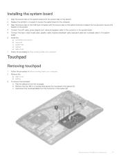
...and installing components 25 c Disconnect the touchpad cable from the connector in After working inside your computer. 2 Remove the: a base cover b battery 3 To remove the touchpad: a Peel the adhesive from the touchpad. Installing the system board 1 Align the screw holes on the system board ... the four M2.0 x 2 screws that secure the touchpad to the system board. 6 Install the: a solid state drive(SSD) b heat sink c system fan d battery e base cover 7 Follow the procedure in the system [2]. Touchpad Removing touchpad 1 Follow the procedure in Before working inside your computer.
...and installing components 25 c Disconnect the touchpad cable from the connector in After working inside your computer. 2 Remove the: a base cover b battery 3 To remove the touchpad: a Peel the adhesive from the touchpad. Installing the system board 1 Align the screw holes on the system board ... the four M2.0 x 2 screws that secure the touchpad to the system board. 6 Install the: a solid state drive(SSD) b heat sink c system fan d battery e base cover 7 Follow the procedure in the system [2]. Touchpad Removing touchpad 1 Follow the procedure in Before working inside your computer.

Ownerss Manual
Page 26
... in the system board [2]. 26 Removing and installing components d Remove the three M2.0 x 2 screws that secure the touchpad support bracket to the touchpad. 5 Install the: a battery b base cover 6 Follow the procedure in After working inside your computer. 2 Remove the: a base cover b WLAN card 3 To remove the display assembly: a Unroute the WLAN...
... in the system board [2]. 26 Removing and installing components d Remove the three M2.0 x 2 screws that secure the touchpad support bracket to the touchpad. 5 Install the: a battery b base cover 6 Follow the procedure in After working inside your computer. 2 Remove the: a base cover b WLAN card 3 To remove the display assembly: a Unroute the WLAN...
Ownerss Manual
Page 35
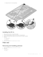
... assembly b WLAN card c base cover 5 Follow the procedure in from the system [4]. d Disconnect the DC-in After working inside your computer. 2 Remove the: a base cover b battery Removing and installing components 35 Palm rest Removing and installing palmrest 1 Follow the procedure in Before working inside your computer.
... assembly b WLAN card c base cover 5 Follow the procedure in from the system [4]. d Disconnect the DC-in After working inside your computer. 2 Remove the: a base cover b battery Removing and installing components 35 Palm rest Removing and installing palmrest 1 Follow the procedure in Before working inside your computer.

Ownerss Manual
Page 36
... the new palm rest: a display assembly b system board c powered button d Input Output(I/O) board e WLAN card f solid state drive(SSD) g heat sink h system fan i touchpad j speaker k battery l base cover 4 Follow the procedure in After working inside your computer.
... the new palm rest: a display assembly b system board c powered button d Input Output(I/O) board e WLAN card f solid state drive(SSD) g heat sink h system fan i touchpad j speaker k battery l base cover 4 Follow the procedure in After working inside your computer.

Ownerss Manual
Page 44
... • Content Type - It's bidirectional, so a device can be USB 2 or USB 3.0. USB Type-C and USB 3.1 USB 3.1 is an industry-supported, uncompressed, all those portable battery packs you used in digital photography and computer graphics • 4K Support - USB Type-C isn't the same thing as an external display - HDMI (High-Definition...
... • Content Type - It's bidirectional, so a device can be USB 2 or USB 3.0. USB Type-C and USB 3.1 USB 3.1 is an industry-supported, uncompressed, all those portable battery packs you used in digital photography and computer graphics • 4K Support - USB Type-C isn't the same thing as an external display - HDMI (High-Definition...

Ownerss Manual
Page 48
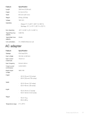
... Resolution 1280 x 720 Pixels (Maximum) Diagonal 74 degrees Storage specification Features Storage: Specification • 128 GB M.2 SSD • 256 GB M.2 SSD • 512 GB M.2 SSD Battery specification Feature Wattage Type Specification 3 Cell, 38 Whr 'smart' Lithium-ion/polymer Li-ion/polymer 48 System specifications
... Resolution 1280 x 720 Pixels (Maximum) Diagonal 74 degrees Storage specification Features Storage: Specification • 128 GB M.2 SSD • 256 GB M.2 SSD • 512 GB M.2 SSD Battery specification Feature Wattage Type Specification 3 Cell, 38 Whr 'smart' Lithium-ion/polymer Li-ion/polymer 48 System specifications
Ownerss Manual
Page 49
...; F) Non-Operating -20° C to 60° C (4° F to 140° F) Typical Amp-hour capacity 3.333 Ahr Typical Watt-hour capacity 38 Whr Coin-cell battery 3 V CR2032 lithium ion cell AC adapter Feature Wattage Input voltage Input current (maximum) Input frequency Output current (continuous) Rated output voltage Height Width Specification 45...
...; F) Non-Operating -20° C to 60° C (4° F to 140° F) Typical Amp-hour capacity 3.333 Ahr Typical Watt-hour capacity 38 Whr Coin-cell battery 3 V CR2032 lithium ion cell AC adapter Feature Wattage Input voltage Input current (maximum) Input frequency Output current (continuous) Rated output voltage Height Width Specification 45...


