User Manual
Page 1
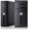
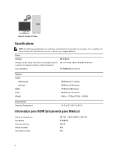
... connectors 18. padlock slot NOTE: The second CD/DVD drive eject button is functional only if a second CD/DVD drive is installed in the computer. Dell Vostro 470 Setup And Features Information About Warnings WARNING: A WARNING indicates a potential for property damage, personal injury, or death. Front And Back View 1. front panel door (open...
... connectors 18. padlock slot NOTE: The second CD/DVD drive eject button is functional only if a second CD/DVD drive is installed in the computer. Dell Vostro 470 Setup And Features Information About Warnings WARNING: A WARNING indicates a potential for property damage, personal injury, or death. Front And Back View 1. front panel door (open...
User Manual
Page 2
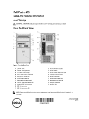
side L/R surround connector 10. VGA connector 13. For additional best practices information, see www.dell.com/regulatory_compliance. Back Panel Figure 2. link integrity light 2. network adapter connector 3. line-in this section, read the safety information that shipped with your computer. S/PDIF ...
side L/R surround connector 10. VGA connector 13. For additional best practices information, see www.dell.com/regulatory_compliance. Back Panel Figure 2. link integrity light 2. network adapter connector 3. line-in this section, read the safety information that shipped with your computer. S/PDIF ...
User Manual
Page 3
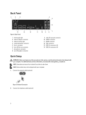
Connect the monitor using either the integrated VGA or HDMI connector. VGA Connector And HDMI Connector 4. Figure 6. Connect the power cable(s). If you purchased the optional discrete graphics card, connect the display to the connector on the monitor and the computer. 3 USB Connection 5. Press the power buttons on the discrete graphics card. Telephone Connection 3. Figure 7. Connect the USB keyboard or mouse (optional). Otherwise, connect the display using only one of the following cables: Figure 5. Connecting Power 6. Figure 4.
Connect the monitor using either the integrated VGA or HDMI connector. VGA Connector And HDMI Connector 4. Figure 6. Connect the power cable(s). If you purchased the optional discrete graphics card, connect the display to the connector on the monitor and the computer. 3 USB Connection 5. Press the power buttons on the discrete graphics card. Telephone Connection 3. Figure 7. Connect the USB keyboard or mouse (optional). Otherwise, connect the display using only one of the following cables: Figure 5. Connecting Power 6. Figure 4.
User Manual
Page 4
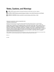
....52 inches) 9.66 kg - 11.22 kg (21.30 lb - 24.74 lb) Environmental Operating Temperature: 10 °C to 35 °C (50 °F to support.dell.com. Power Wattage 350 W/460 W Voltage (see the safety information that shipped with your 100 V-127 V/200 V-240 V, 50 Hz/60 Hz, 8 A/4 A computer for your...
....52 inches) 9.66 kg - 11.22 kg (21.30 lb - 24.74 lb) Environmental Operating Temperature: 10 °C to 35 °C (50 °F to support.dell.com. Power Wattage 350 W/460 W Voltage (see the safety information that shipped with your 100 V-127 V/200 V-240 V, 50 Hz/60 Hz, 8 A/4 A computer for your...

User Manual
Page 5
... Windows Vista start button, and Office Outlook® are trademarks of Dell Inc. Other trademarks and trade names may be used in this text: Dell™, the DELL logo, Dell Precision™, Precision ON™,ExpressCharge™, Latitude™, Latitude ON™, OptiPlex™, Vostro™, and Wi-Fi Catcher™ are either the entities...
... Windows Vista start button, and Office Outlook® are trademarks of Dell Inc. Other trademarks and trade names may be used in this text: Dell™, the DELL logo, Dell Precision™, Precision ON™,ExpressCharge™, Latitude™, Latitude ON™, OptiPlex™, Vostro™, and Wi-Fi Catcher™ are either the entities...
Owner's Manual
Page 2
...for property damage, personal injury, or death. Trademarks used in this text: Dell™, the DELL logo, Dell Precision™, Precision ON™,ExpressCharge™, Latitude™, Latitude ON™, OptiPlex™, Vostro™, and Wi-Fi Catcher™ are either the entities claiming the ...marks and names or their products, Dell Inc. Microsoft®, Windows®, MS-DOS®, Windows Vista®, ...
...for property damage, personal injury, or death. Trademarks used in this text: Dell™, the DELL logo, Dell Precision™, Precision ON™,ExpressCharge™, Latitude™, Latitude ON™, OptiPlex™, Vostro™, and Wi-Fi Catcher™ are either the entities claiming the ...marks and names or their products, Dell Inc. Microsoft®, Windows®, MS-DOS®, Windows Vista®, ...

Owner's Manual
Page 3
Contents Notes, Cautions, and Warnings 2 1 Working on Your Computer...5 Before Working Inside Your Computer...5 Recommended Tools...6 Turning Off Your Computer...6 After Working Inside Your Computer...6 2 Removing The Cover...7 Installing The Cover...8 3 Removing The Memory...9 Installing The Memory...9 4 Removing The Expansion Card 11 Installing The Expansion Card...12 5 Removing The Optical Disk Drive 13 Installing The Optical Disk Drive...14 6 Removing The Hard Disk Drive 15 Installing The Hard Disk Drive...16 7 Removing The Memory Card Reader 19 Installing The Memory Card Reader...20 ...
Contents Notes, Cautions, and Warnings 2 1 Working on Your Computer...5 Before Working Inside Your Computer...5 Recommended Tools...6 Turning Off Your Computer...6 After Working Inside Your Computer...6 2 Removing The Cover...7 Installing The Cover...8 3 Removing The Memory...9 Installing The Memory...9 4 Removing The Expansion Card 11 Installing The Expansion Card...12 5 Removing The Optical Disk Drive 13 Installing The Optical Disk Drive...14 6 Removing The Hard Disk Drive 15 Installing The Hard Disk Drive...16 7 Removing The Memory Card Reader 19 Installing The Memory Card Reader...20 ...
Owner's Manual
Page 4
... Advanced...51 Security...53 Boot...53 Exit...53 20 Diagnostic Error Messages 55 Diagnostic Beep Codes...56 System Messages...56 21 Specifications...59 22 Contacting Dell...63 Contacting Dell...63
... Advanced...51 Security...53 Boot...53 Exit...53 20 Diagnostic Error Messages 55 Diagnostic Beep Codes...56 System Messages...56 21 Specifications...59 22 Contacting Dell...63 Contacting Dell...63
Owner's Manual
Page 5
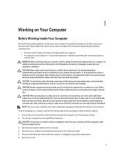
... that shipped with your computer, read the safety information that both connectors are disconnecting this type of the computer. Ensure that is not authorized by Dell is not covered by performing the removal procedure in this document. Remove the cover. 5 1 Working on the cable itself. WARNING: Before working inside ...the following conditions exist: • You have connectors with locking tabs; NOTE: The color of your computer (see the Regulatory Compliance Homepage at www.dell.com/ regulatory_compliance. Disconnect all attached devices from the network device. 3.
... that shipped with your computer, read the safety information that both connectors are disconnecting this type of the computer. Ensure that is not authorized by Dell is not covered by performing the removal procedure in this document. Remove the cover. 5 1 Working on the cable itself. WARNING: Before working inside ...the following conditions exist: • You have connectors with locking tabs; NOTE: The color of your computer (see the Regulatory Compliance Homepage at www.dell.com/ regulatory_compliance. Disconnect all attached devices from the network device. 3.
Owner's Manual
Page 6
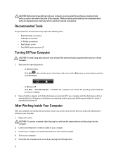
... computer. 1. Recommended Tools The procedures in the lower-right corner of the computer. CAUTION: Before touching anything inside your computer, ground yourself by running the Dell Diagnostics. 6 The computer turns off . While you turn them off after the operating system shutdown process is complete. 2.
... computer. 1. Recommended Tools The procedures in the lower-right corner of the computer. CAUTION: Before touching anything inside your computer, ground yourself by running the Dell Diagnostics. 6 The computer turns off . While you turn them off after the operating system shutdown process is complete. 2.

Owner's Manual
Page 7
Slide the computer cover towards the back of the computer, and then remove it from the computer. 7 Figure 2. 4. Figure 1. 3. Lift the computer cover away from the computer. Remove the two thumbscrews securing the computer cover to the computer. Follow the procedures in Before working Inside your computer. 2. 2 Removing The Cover 1.
Slide the computer cover towards the back of the computer, and then remove it from the computer. 7 Figure 2. 4. Figure 1. 3. Lift the computer cover away from the computer. Remove the two thumbscrews securing the computer cover to the computer. Follow the procedures in Before working Inside your computer. 2. 2 Removing The Cover 1.
Owner's Manual
Page 8
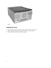
Installing The Cover 1. Place the computer cover on the computer. 3. Figure 3. Follow the procedures in After Working Inside Your Computer. 8 Replace and tighten the thumbscrews that secure the computer cover on the computer and slide it inwards from the back of the computer. 2.
Installing The Cover 1. Place the computer cover on the computer. 3. Figure 3. Follow the procedures in After Working Inside Your Computer. 8 Replace and tighten the thumbscrews that secure the computer cover on the computer and slide it inwards from the back of the computer. 2.
Owner's Manual
Page 9
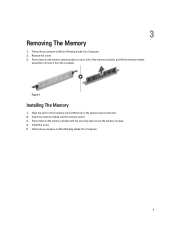
Align the notch on the memory-card with the tab in Before Working Inside Your Computer. 2. 3 Removing The Memory 1. Follow the procedures in the system-board connector. 2. Install the cover. 5. Press down on each side of the memory modules and lift the memory module upwards to remove it from the computer. Figure 4. Follow the procedures in place. 4. Remove the cover. 3. Press down on the memory retaining tabs on the memory module until the securing clips secure the memory in After Working Inside Your Computer. 9 Insert the memory module into the memory socket. 3. ...
Align the notch on the memory-card with the tab in Before Working Inside Your Computer. 2. 3 Removing The Memory 1. Follow the procedures in the system-board connector. 2. Install the cover. 5. Press down on each side of the memory modules and lift the memory module upwards to remove it from the computer. Figure 4. Follow the procedures in place. 4. Remove the cover. 3. Press down on the memory retaining tabs on the memory module until the securing clips secure the memory in After Working Inside Your Computer. 9 Insert the memory module into the memory socket. 3. ...
Owner's Manual
Page 11
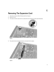
Remove the cover. 3. Press down the latch and pull the expansion card away from the computer. Figure 6. 11 Press down on the blue retainer tab in Before Working Inside Your Computer. 2. 4 Removing The Expansion Card 1. Figure 5. 4. Follow the procedures in an outward direction and push the retention panel downwards.
Remove the cover. 3. Press down the latch and pull the expansion card away from the computer. Figure 6. 11 Press down on the blue retainer tab in Before Working Inside Your Computer. 2. 4 Removing The Expansion Card 1. Figure 5. 4. Follow the procedures in an outward direction and push the retention panel downwards.

Owner's Manual
Page 12
Install the expansion card retainer module to the chassis. 3. Push the expansion card into the card slot and secure the latch. 2. Installing The Expansion Card 1. Install the cover. 4. Follow the procedures in After Working Inside Your Computer. 12
Install the expansion card retainer module to the chassis. 3. Push the expansion card into the card slot and secure the latch. 2. Installing The Expansion Card 1. Install the cover. 4. Follow the procedures in After Working Inside Your Computer. 12
Owner's Manual
Page 13
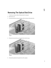
Remove the cover. 3. Disconnect the power cable and the data cable from the back of the computer. 13 5 Removing The Optical Disk Drive 1. Remove the screws that secure the optical drive to the drive cage. Slide out the optical drive through the front of the optical drive. Figure 7. 4. Follow the procedures in Before Working Inside Your Computer. 2. Figure 8. 5.
Remove the cover. 3. Disconnect the power cable and the data cable from the back of the computer. 13 5 Removing The Optical Disk Drive 1. Remove the screws that secure the optical drive to the drive cage. Slide out the optical drive through the front of the optical drive. Figure 7. 4. Follow the procedures in Before Working Inside Your Computer. 2. Figure 8. 5.
Owner's Manual
Page 14
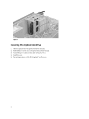
Connect the power cable and data cable to the drive cage. 3. Slide the optical drive in After Working Inside Your Computer. 14 Install the cover. 5. Replace the screws that secure the optical drive to the optical drive. 4. Follow the procedures in through the front of the computer. 2. Figure 9. Installing The Optical Disk Drive 1.
Connect the power cable and data cable to the drive cage. 3. Slide the optical drive in After Working Inside Your Computer. 14 Install the cover. 5. Replace the screws that secure the optical drive to the optical drive. 4. Follow the procedures in through the front of the computer. 2. Figure 9. Installing The Optical Disk Drive 1.
Owner's Manual
Page 15
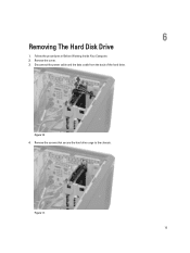
Disconnect the power cable and the data cable from the back of the hard drive. Remove the screws that secure the hard drive cage to the chassis. Figure 10. 4. 6 Removing The Hard Disk Drive 1. Figure 11. 15 Remove the cover. 3. Follow the procedures in Before Working Inside Your Computer. 2.
Disconnect the power cable and the data cable from the back of the hard drive. Remove the screws that secure the hard drive cage to the chassis. Figure 10. 4. 6 Removing The Hard Disk Drive 1. Figure 11. 15 Remove the cover. 3. Follow the procedures in Before Working Inside Your Computer. 2.
Owner's Manual
Page 16
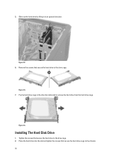
Remove the screws that secure the hard drive to the drive cage. Pry the hard drive cage in an upward direction. Slide out the hard drive by lifting it in the direction indicated to the chassis. 16 Tighten the screws that secure the hard drive to the drive cage. 2. Figure 12. 6. Place the hard drive into the slot and tighten the screws that secure the hard drive cage to remove the hard drive from the hard drive cage. Installing The Hard Disk Drive 1. 5. Figure 13. 7. Figure 14.
Remove the screws that secure the hard drive to the drive cage. Pry the hard drive cage in an upward direction. Slide out the hard drive by lifting it in the direction indicated to the chassis. 16 Tighten the screws that secure the hard drive to the drive cage. 2. Figure 12. 6. Place the hard drive into the slot and tighten the screws that secure the hard drive cage to remove the hard drive from the hard drive cage. Installing The Hard Disk Drive 1. 5. Figure 13. 7. Figure 14.

Owner's Manual
Page 17
Install the cover. 5. Follow the procedures in After Working Inside Your Computer. 17 3. Connect the power cable and data cable to the hard drive. 4.
Install the cover. 5. Follow the procedures in After Working Inside Your Computer. 17 3. Connect the power cable and data cable to the hard drive. 4.
