
Service Manual
Page 37
... Working on the power supply retention clips. 1 screws (4) (only 3 screws for the Vostro 420, Vostro 220, and Vostro 220s computers; For the Vostro 220s: a. Press down on Your Computer. 2. Disengage the cables from the system board and drives. Back to Contents Page Power Supply Dell™ Vostro™ 420/220/220s Service Manual Removing the Power Supply Replacing the Power Supply DC Power Supply Connectors DC Power Supply Connector Pin Assignments...
... Working on the power supply retention clips. 1 screws (4) (only 3 screws for the Vostro 420, Vostro 220, and Vostro 220s computers; For the Vostro 220s: a. Press down on Your Computer. 2. Disengage the cables from the system board and drives. Back to Contents Page Power Supply Dell™ Vostro™ 420/220/220s Service Manual Removing the Power Supply Replacing the Power Supply DC Power Supply Connectors DC Power Supply Connector Pin Assignments...
Service Manual
Page 38
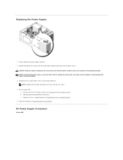
... as these screws are secure. 4. DC Power Supply Connectors Vostro 420 The cables must be properly routed to the system board and drives. b. Follow the procedure in After Working on Your Computer. Replacing the Power Supply 1. NOTE: Double-check all screws may cause electrical shock as you insert them into the routing clips (if present). Reinstall any...
... as these screws are secure. 4. DC Power Supply Connectors Vostro 420 The cables must be properly routed to the system board and drives. b. Follow the procedure in After Working on Your Computer. Replacing the Power Supply 1. NOTE: Double-check all screws may cause electrical shock as you insert them into the routing clips (if present). Reinstall any...
Service Manual
Page 44
... processor heat sink/fan assembly (see System Board Components for connector locations). 8. Install all the data cables from the drives to Contents Page Connect the power supply cables to the system board as required. 9. Connect any additional cables to the system board (see Replacing the Processor Heat Sink/Fan Assembly). 5.
... processor heat sink/fan assembly (see System Board Components for connector locations). 8. Install all the data cables from the drives to Contents Page Connect the power supply cables to the system board as required. 9. Connect any additional cables to the system board (see Replacing the Processor Heat Sink/Fan Assembly). 5.


