
Dell Vostro 3901 Owners Manual
Page 3
...12 Installing the Optical Drive...12 Removing the Card Reader...13 Installing the Card Reader...13 Removing the Memory...13 Installing the Memory...14 Removing the Heatsink...14 Installing the Heatsink...15 Removing the Processor...15 Installing the Processor...16 Removing the Expansion Card(s)...16 Installing the Expansion Card(s)...17 Removing the Power Supply Unit (PSU 17 Installing the Power Supply Unit (PSU 18 Removing the Power Switch...18 Installing the Power Switch...19 Removing the Input/Output (I/O) Panel 19 Installing the Input/Output (I/O) Panel 20 Removing the Wireless Device...
...12 Installing the Optical Drive...12 Removing the Card Reader...13 Installing the Card Reader...13 Removing the Memory...13 Installing the Memory...14 Removing the Heatsink...14 Installing the Heatsink...15 Removing the Processor...15 Installing the Processor...16 Removing the Expansion Card(s)...16 Installing the Expansion Card(s)...17 Removing the Power Supply Unit (PSU 17 Installing the Power Supply Unit (PSU 18 Removing the Power Switch...18 Installing the Power Switch...19 Removing the Input/Output (I/O) Panel 19 Installing the Input/Output (I/O) Panel 20 Removing the Wireless Device...
Dell Vostro 3901 Owners Manual
Page 4
Installing the System Fan...22 Removing the System Board...22 Installing the System Board...23 System Board Components...23 3 Troubleshooting Your Computer 25 Diagnostic Power LED Codes...25 Diagnostic Error Messages...26 System Error Messages...30 4 System Setup Options 31 Main...31 Advanced...32 Boot...32 Power...33 Security...33 Exit...33 System Setup Overview...33 Enter System Setup...34 5 Specifications...35 6 Contacting Dell 38
Installing the System Fan...22 Removing the System Board...22 Installing the System Board...23 System Board Components...23 3 Troubleshooting Your Computer 25 Diagnostic Power LED Codes...25 Diagnostic Error Messages...26 System Error Messages...30 4 System Setup Options 31 Main...31 Advanced...32 Boot...32 Power...33 Security...33 Exit...33 System Setup Overview...33 Enter System Setup...34 5 Specifications...35 6 Contacting Dell 38
Dell Vostro 3901 Owners Manual
Page 5
... before connecting to avoid bending any connector pins. Unless otherwise noted, each procedure included in your product documentation, or as a processor by its edges, not by its metal mounting bracket. You should only perform troubleshooting and simple repairs as authorized in this document. Also, before opening the computer cover or panels. WARNING: Before working inside the computer. 1. CAUTION: Handle components and cards...
... before connecting to avoid bending any connector pins. Unless otherwise noted, each procedure included in your product documentation, or as a processor by its edges, not by its metal mounting bracket. You should only perform troubleshooting and simple repairs as authorized in this document. Also, before opening the computer cover or panels. WARNING: Before working inside the computer. 1. CAUTION: Handle components and cards...
Dell Vostro 3901 Owners Manual
Page 6
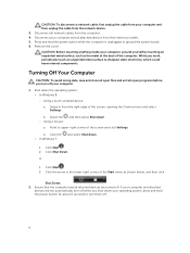
... network cables from the right edge of the screen, opening the Charms menu and select Settings. Shut down your computer. 1. b. b. Point to turn off . Press and hold the power button for about 6 seconds to upper-right corner of the computer. Click Start . 2. CAUTION: Before touching anything inside your computer and all open programs before you turn off your operating system, press and hold the power button...
... network cables from the right edge of the screen, opening the Charms menu and select Settings. Shut down your computer. 1. b. b. Point to turn off . Press and hold the power button for about 6 seconds to upper-right corner of the computer. Click Start . 2. CAUTION: Before touching anything inside your computer and all open programs before you turn off your operating system, press and hold the power button...

Dell Vostro 3901 Owners Manual
Page 7
Connect any external devices, cards, and cables before turning on your computer. 3. Turn on your computer and all attached devices to your computer. 5. Connect your computer. 1. Replace the cover. After Working Inside Your Computer After you complete any replacement procedure, ensure you connect any telephone or network cables to their electrical outlets. 4. CAUTION: To connect a network cable, first plug the cable into the network device and then plug it into the computer. 2. If required, verify that the computer works correctly by running the Dell Diagnostics. 7
Connect any external devices, cards, and cables before turning on your computer. 3. Turn on your computer and all attached devices to your computer. 5. Connect your computer. 1. Replace the cover. After Working Inside Your Computer After you complete any replacement procedure, ensure you connect any telephone or network cables to their electrical outlets. 4. CAUTION: To connect a network cable, first plug the cable into the network device and then plug it into the computer. 2. If required, verify that the computer works correctly by running the Dell Diagnostics. 7

Dell Vostro 3901 Owners Manual
Page 9
... remove the bezel: a. Removing the Bezel 1. c. I/O board 7. coin-cell battery 10. b. Release the hooks on the chassis. 2. 3. Slide the computer cover towards the back of the bezel from the computer. 9 card reader 6. Follow the procedures in After Working Inside Your Computer. Follow the steps to the computer. Pry the front panel retention clips away from the computer [2]. hard drive 9. optical drive 5. Installing the Cover 1. heatsink 4. VGA card 11. power-switch board...
... remove the bezel: a. Removing the Bezel 1. c. I/O board 7. coin-cell battery 10. b. Release the hooks on the chassis. 2. 3. Slide the computer cover towards the back of the bezel from the computer. 9 card reader 6. Follow the procedures in After Working Inside Your Computer. Follow the steps to the computer. Pry the front panel retention clips away from the computer [2]. hard drive 9. optical drive 5. Installing the Cover 1. heatsink 4. VGA card 11. power-switch board...

Dell Vostro 3901 Owners Manual
Page 12
...hard drive into its slot in After Working Inside Your Computer. Connect the SATA cable and the power cable to remove the optical drive: a. Install the: • bezel • cover 7. Follow the procedures in the computer. 4. Remove the: • cover • bezel 3. Install the screws that secure the hard drive to the optical drive. 4. Install the screws that secure the optical drive. 3. Installing the Optical Drive 1. Replace the hard drive into place. 2. Removing the Optical Drive 1. Follow the procedures in Before Working Inside Your Computer. 2. b. Install...
...hard drive into its slot in After Working Inside Your Computer. Connect the SATA cable and the power cable to remove the optical drive: a. Install the: • bezel • cover 7. Follow the procedures in the computer. 4. Remove the: • cover • bezel 3. Install the screws that secure the hard drive to the optical drive. 4. Install the screws that secure the optical drive. 3. Installing the Optical Drive 1. Replace the hard drive into place. 2. Removing the Optical Drive 1. Follow the procedures in Before Working Inside Your Computer. 2. b. Install...

Dell Vostro 3901 Owners Manual
Page 13
.... 2. Connect the card reader power cable to the chassis. 3. Install the: • bezel • cover 6. Follow the procedures in Before Working Inside Your Computer. 2. Follow the procedures in Before Working Inside Your Computer. 2. Push the card reader towards the front of the computer. e. Follow the procedures in After Working Inside Your Computer. Remove the: • cover • bezel 3. Remove the screws that secure the card reader to the system board. 5. Removing the Memory...
.... 2. Connect the card reader power cable to the chassis. 3. Install the: • bezel • cover 6. Follow the procedures in Before Working Inside Your Computer. 2. Follow the procedures in Before Working Inside Your Computer. 2. Push the card reader towards the front of the computer. e. Follow the procedures in After Working Inside Your Computer. Remove the: • cover • bezel 3. Remove the screws that secure the card reader to the system board. 5. Removing the Memory...

Dell Vostro 3901 Owners Manual
Page 18
b. Replace the screws to the computer. 3. Push-in Before Working Inside Your Computer. 2. Connect the power cables to remove the power switch: a. Follow the procedures in on the two latches and pulling it out from the metal retention clip [2]. Slide the power supply unit towards the back of the computer until to secure the power supply until it from the system board [1]. Install the cover. 5. Slide the...
b. Replace the screws to the computer. 3. Push-in Before Working Inside Your Computer. 2. Connect the power cables to remove the power switch: a. Follow the procedures in on the two latches and pulling it out from the metal retention clip [2]. Slide the power supply unit towards the back of the computer until to secure the power supply until it from the system board [1]. Install the cover. 5. Slide the...

Dell Vostro 3901 Owners Manual
Page 22
... Working Inside Your Computer. Connect the fan cable to the computer. Push the system fan inwards and remove it from the system board. Installing the System Fan 1. Removing the System Board 1. Disconnect the fan cable from the computer. Install the cover. 5. Remove the screws that secure the system fan to the system board. 4. b. Remove the: • cover • bezel • optical drive • hard drive • heatsink • processor • memory • expansion cards 22 Remove the cover. 3. Removing the System Fan...
... Working Inside Your Computer. Connect the fan cable to the computer. Push the system fan inwards and remove it from the system board. Installing the System Fan 1. Removing the System Board 1. Disconnect the fan cable from the computer. Install the cover. 5. Remove the screws that secure the system fan to the system board. 4. b. Remove the: • cover • bezel • optical drive • hard drive • heatsink • processor • memory • expansion cards 22 Remove the cover. 3. Removing the System Fan...

Dell Vostro 3901 Owners Manual
Page 25
... working by testing it with another device, such as a lamp. If the computer is plugged into a power strip, ensure the power strip is plugged into an electrical outlet and is not receiving power or in Hibernation mode. • • Re-seat the power cable in the On state. Computer fails to the motherboard and processor. 3 Troubleshooting Your Computer You can troubleshoot your computer using indicators like Diagnostic Lights, Beep Codes...
... working by testing it with another device, such as a lamp. If the computer is plugged into a power strip, ensure the power strip is plugged into an electrical outlet and is not receiving power or in Hibernation mode. • • Re-seat the power cable in the On state. Computer fails to the motherboard and processor. 3 Troubleshooting Your Computer You can troubleshoot your computer using indicators like Diagnostic Lights, Beep Codes...
Dell Vostro 3901 Owners Manual
Page 26
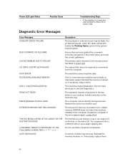
... A20 FAILURE Description The touchpad or external mouse may be loose. The hard drive failed initialization. Run the hard drive tests in filenames. Reinsert the card or try another card. If the error appears again, contact Dell. The file that you are trying to copy is too large to a different disk or use these characters in the Dell Diagnostics. The primary cache internal to commands from the computer. A memory...
... A20 FAILURE Description The touchpad or external mouse may be loose. The hard drive failed initialization. Run the hard drive tests in filenames. Reinsert the card or try another card. If the error appears again, contact Dell. The file that you are trying to copy is too large to a different disk or use these characters in the Dell Diagnostics. The primary cache internal to commands from the computer. A memory...
Dell Vostro 3901 Owners Manual
Page 27
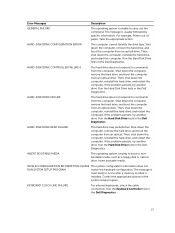
... external keyboards, check the cable connection. Run the Hard Disk Drive tests in the Dell Diagnostics. HARD-DISK DRIVE FAILURE The hard drive does not respond to carry out the command. Run the Hard Disk Drive tests in the Dell Diagnostics. Correct the appropriate options in the Dell Diagnostics. 27 Run the Keyboard Controller test in the system setup program. Shut down the computer, remove the hard drive, and boot the computer from an optical. The message is unable to commands from an optical drive. Error Messages Description GENERAL FAILURE The operating...
... external keyboards, check the cable connection. Run the Hard Disk Drive tests in the Dell Diagnostics. HARD-DISK DRIVE FAILURE The hard drive does not respond to carry out the command. Run the Hard Disk Drive tests in the Dell Diagnostics. Correct the appropriate options in the Dell Diagnostics. 27 Run the Keyboard Controller test in the system setup program. Shut down the computer, remove the hard drive, and boot the computer from an optical. The message is unable to commands from an optical drive. Error Messages Description GENERAL FAILURE The operating...

Dell Vostro 3901 Owners Manual
Page 28
... the hard drive is your boot device, ensure that the drive is conflicting with the operating system, another program, or a utility. Run theKeyboard Controller test in the Dell Diagnostics. For external keyboards or keypads, check the cable connection. Run the Stuck Key test in the Dell Diagnostics. If the error message still appears, see the software documentation. Run the System Set tests in the Dell Diagnostics. The software you are attempting to run is installed, properly seated, and partitioned as a boot device. Reinstall the memory...
... the hard drive is your boot device, ensure that the drive is conflicting with the operating system, another program, or a utility. Run theKeyboard Controller test in the Dell Diagnostics. For external keyboards or keypads, check the cable connection. Run the Stuck Key test in the Dell Diagnostics. If the error message still appears, see the software documentation. Run the System Set tests in the Dell Diagnostics. The software you are attempting to run is installed, properly seated, and partitioned as a boot device. Reinstall the memory...
Dell Vostro 3901 Owners Manual
Page 29
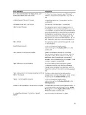
... The reserve battery that you want to use. Run the System Memory tests and the Keyboard Controller test in the contact Dell . See Windows Help and Support for the Date and Time options. SHUTDOWN FAILURE A chip on the hard drive. If the problem persists, try again. 29 Connect your computer to an electrical outlet to charge the battery. Contact Dell. Run the System Set tests in the System Setup or contact Dell. Connect your computer...
... The reserve battery that you want to use. Run the System Memory tests and the Keyboard Controller test in the contact Dell . See Windows Help and Support for the Date and Time options. SHUTDOWN FAILURE A chip on the hard drive. If the problem persists, try again. 29 Connect your computer to an electrical outlet to charge the battery. Contact Dell. Run the System Set tests in the System Setup or contact Dell. Connect your computer...

Dell Vostro 3901 Owners Manual
Page 30
... the cables are connected and that the drive is installed properly and partitioned as a boot device. • Enter system setup and ensure that the boot sequence information is correct. S.M.A.R.T error, possible hard disk drive failure. 30 CMOS checksum error RTC is your data regularly. If reseating the cable does not solve the problem, replace the keyboard. Dell recommends that a parameter has exceeded its normal operating range. Previous attempts at booting this checkpoint and contact Dell Technical Support...
... the cables are connected and that the drive is installed properly and partitioned as a boot device. • Enter system setup and ensure that the boot sequence information is correct. S.M.A.R.T error, possible hard disk drive failure. 30 CMOS checksum error RTC is your data regularly. If reseating the cable does not solve the problem, replace the keyboard. Dell recommends that a parameter has exceeded its normal operating range. Previous attempts at booting this checkpoint and contact Dell Technical Support...

Dell Vostro 3901 Owners Manual
Page 31
...Memory Installed Memory Available Memory Running Speed Memory Technology SATA Information SATA 0 SATA 1 SATA 2 SATA 3 Displays the BIOS revision. Displays the model name of your computer (if available). Resets the time on the computer's internal calendar. Displays the service tag of the system. Displays the processor core count. Displays the available memory. Displays the memory type and technology. Displays the model number and capacity of your computer. Resets the date on the computer's internal clock. Displays the processor ID. Displays the asset tag of the hard drive...
...Memory Installed Memory Available Memory Running Speed Memory Technology SATA Information SATA 0 SATA 1 SATA 2 SATA 3 Displays the BIOS revision. Displays the model name of your computer (if available). Resets the time on the computer's internal calendar. Displays the service tag of the system. Displays the processor core count. Displays the available memory. Displays the memory type and technology. Displays the model number and capacity of your computer. Resets the date on the computer's internal clock. Displays the processor ID. Displays the asset tag of the hard drive...

Dell Vostro 3901 Owners Manual
Page 32
... Keyboard Errors USB Boot Support Boot Mode 1st Boot Device 2nd Boot Device 3rd Boot Device Allows you to select the boot mode. Allows you to enable or disable the numlock key during Boot. Allows you to enable or disable the boot device. 32 Allows you to enable or disable the boot device. Advanced Processor Configuration AMD Cool 'N' Quiet Secure Virtual Machine Mode USB Configuration Front USB Ports Rear USB Ports Onboard Device Configuration Onboard Audio Controller SATA Mode Onboard LAN Controller Onboard LAN Boot ROM Allows you to enable or disable the displaying keyboard errors...
... Keyboard Errors USB Boot Support Boot Mode 1st Boot Device 2nd Boot Device 3rd Boot Device Allows you to select the boot mode. Allows you to enable or disable the numlock key during Boot. Allows you to enable or disable the boot device. 32 Allows you to enable or disable the boot device. Advanced Processor Configuration AMD Cool 'N' Quiet Secure Virtual Machine Mode USB Configuration Front USB Ports Rear USB Ports Onboard Device Configuration Onboard Audio Controller SATA Mode Onboard LAN Controller Onboard LAN Boot ROM Allows you to enable or disable the displaying keyboard errors...
Dell Vostro 3901 Owners Manual
Page 33
... add, change, or remove any hardware in your computer. • set or change a user-selectable option such as the user password. • read the current amount of memory or set the type of hard drive installed. 33 System Setup Overview System Setup allows you to: • change the system configuration information after you to save, discard, and load default settings before exiting from System Setup. Displays information about CD/DVD ROM drivers. Allows you to enable or disable the HDD...
... add, change, or remove any hardware in your computer. • set or change a user-selectable option such as the user password. • read the current amount of memory or set the type of hard drive installed. 33 System Setup Overview System Setup allows you to: • change the system configuration information after you to save, discard, and load default settings before exiting from System Setup. Displays information about CD/DVD ROM drivers. Allows you to enable or disable the HDD...

Dell Vostro 3901 Owners Manual
Page 37
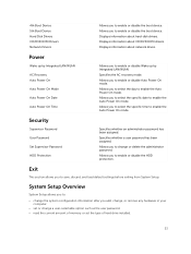
... data to 60 Hz 200 W 3.0 A NOTE: Total power output of the computer; steady / blinking amber light indicates a problem with the system board. solid white light indicates sleep state of +5 V and +3.30 V can not exceed 80 W. blinking white light indicates that the computer is calculated by ISA-S71.04-1985 37 solid white light indicates power-on state. blinking white light - Control Lights And Diagnostic Lights power button light drive activity light white light -
... data to 60 Hz 200 W 3.0 A NOTE: Total power output of the computer; steady / blinking amber light indicates a problem with the system board. solid white light indicates sleep state of +5 V and +3.30 V can not exceed 80 W. blinking white light indicates that the computer is calculated by ISA-S71.04-1985 37 solid white light indicates power-on state. blinking white light - Control Lights And Diagnostic Lights power button light drive activity light white light -


