
Service Manual with optical drive
Page 3
... USB features...12 Intel Optane memory...13 Enabling Intel Optane memory...14 Disabling Intel Optane memory...14 3 Removing and installing components 15 Recommended tools...15 Screw list...15 Micro SD card...16 Removing the micro SD card...16 Installing the micro SD card...17 Optical drive...18 Removing the optical drive...18 Installing optical drive ...19 Base cover...20 Removing the base cover...20 Installing the base cover...22 Battery...23 Removing the battery...23 Installing the battery...24 Memory modules...
... USB features...12 Intel Optane memory...13 Enabling Intel Optane memory...14 Disabling Intel Optane memory...14 3 Removing and installing components 15 Recommended tools...15 Screw list...15 Micro SD card...16 Removing the micro SD card...16 Installing the micro SD card...17 Optical drive...18 Removing the optical drive...18 Installing optical drive ...19 Base cover...20 Removing the base cover...20 Installing the base cover...22 Battery...23 Removing the battery...23 Installing the battery...24 Memory modules...

Service Manual with optical drive
Page 4
... reader 61 Display bezel...61 Removing the display bezel...61 Installing the display bezel ...62 Camera...63 Removing the camera...63 Installing the camera...64 Display panel...65 Removing the display panel...65 Installation display panel...67 Display hinges...69 Removing the display hinges...69 Installing the display hinges...70 Display cable...71 Removing the display cable...71 Installing the display cable...72 Power button board...73 Removing the power button board...73 Installing the power button board...74 Power button...75 Removing the power button...75 Installing the power button...
... reader 61 Display bezel...61 Removing the display bezel...61 Installing the display bezel ...62 Camera...63 Removing the camera...63 Installing the camera...64 Display panel...65 Removing the display panel...65 Installation display panel...67 Display hinges...69 Removing the display hinges...69 Installing the display hinges...70 Display cable...71 Removing the display cable...71 Installing the display cable...72 Power button board...73 Removing the power button board...73 Installing the power button board...74 Power button...75 Removing the power button...75 Installing the power button...

Service Manual with optical drive
Page 6
... before you begin working inside the computer, replace all power sources before connecting to perform any connector pins. 1 Working on your computer Safety instructions Use the following conditions exist: • You have connectors with locking tabs; NOTE: Disconnect all covers, panels, and screws before opening the computer cover or panels. You should only perform troubleshooting and simple repairs as authorized in on a card. Hold a component such...
... before you begin working inside the computer, replace all power sources before connecting to perform any connector pins. 1 Working on your computer Safety instructions Use the following conditions exist: • You have connectors with locking tabs; NOTE: Disconnect all covers, panels, and screws before opening the computer cover or panels. You should only perform troubleshooting and simple repairs as authorized in on a card. Hold a component such...

Service Manual with optical drive
Page 7
... system board, you must remove the main battery before opening the display. Press the power button to recognize and troubleshoot is properly grounded. CAUTION: To guard against electrical shock, always unplug your back. 4. CAUTION: Before touching anything inside your spine when you are ready to ESD damage. • Handle all static-sensitive components in previous Dell products. Very slight charges can...
... system board, you must remove the main battery before opening the display. Press the power button to recognize and troubleshoot is properly grounded. CAUTION: To guard against electrical shock, always unplug your back. 4. CAUTION: Before touching anything inside your spine when you are ready to ESD damage. • Handle all static-sensitive components in previous Dell products. Very slight charges can...

Service Manual with optical drive
Page 8
... strap prior to avoid accidental ESD hardware damage. Follow the same techniques in static-safe packaging. Use only Field Service kits with a wrist strap tester in order to each service call, and at the customer location. However, you connect external devices, cards, and cables before physically handling any bare metal on the system being repaired. Always place parts in your body to keep sensitive...
... strap prior to avoid accidental ESD hardware damage. Follow the same techniques in static-safe packaging. Use only Field Service kits with a wrist strap tester in order to each service call, and at the customer location. However, you connect external devices, cards, and cables before physically handling any bare metal on the system being repaired. Always place parts in your body to keep sensitive...

Service Manual with optical drive
Page 9
..., use batteries designed for this particular Dell computer. Steps 1. Connect your computer and all attached devices to your computer. Working on your computer 9 Connect any cards, such as an ExpressCard. 2. Connect any external devices, such as a port replicator or media base, and replace any telephone or network cables to their electrical outlets. 4. CAUTION: To connect a network cable, first plug the cable into the network device and then plug it into the computer. 3. Turn...
..., use batteries designed for this particular Dell computer. Steps 1. Connect your computer and all attached devices to your computer. Working on your computer 9 Connect any cards, such as an ExpressCard. 2. Connect any external devices, such as a port replicator or media base, and replace any telephone or network cables to their electrical outlets. 4. CAUTION: To connect a network cable, first plug the cable into the network device and then plug it into the computer. 3. Turn...

Service Manual with optical drive
Page 11
... users to 1080p • Automotive Connection System - A new, smaller connector for additional color models used in tuner to send audio data "upstream" to help with the advantages. HDMI supports standard, enhanced, or high-definition video, plus multichannel digital audio on the system display the new ON-FLASH-FLASH or ON-FLASH-ON failure code. Enables video resolutions far beyond 1080p, supporting next-generation displays that will provide 5.1 channel audio support. Curved edge Memory Errors Memory errors...
... users to 1080p • Automotive Connection System - A new, smaller connector for additional color models used in tuner to send audio data "upstream" to help with the advantages. HDMI supports standard, enhanced, or high-definition video, plus multichannel digital audio on the system display the new ON-FLASH-FLASH or ON-FLASH-ON failure code. Enables video resolutions far beyond 1080p, supporting next-generation displays that will provide 5.1 channel audio support. Curved edge Memory Errors Memory errors...

Service Manual with optical drive
Page 12
... Speed Introduction Year 2000 USB 3.0/USB 3.1 Gen 1 5 Gbps Super Speed 2010 USB 3.1 Gen 2 10 Gbps Super Speed 2013 USB 3.0/USB 3.1 Gen 1 (SuperSpeed USB) For years, the USB 2.0 has been firmly entrenched as a DVD player) and the DTV, enabling new functionality USB features Universal Serial Bus, or USB, was introduced in parallel with the existing USB 2.0 bus (refer to better accommodate power-hungry devices • New power management features • Full...
... Speed Introduction Year 2000 USB 3.0/USB 3.1 Gen 1 5 Gbps Super Speed 2010 USB 3.1 Gen 2 10 Gbps Super Speed 2013 USB 3.0/USB 3.1 Gen 1 (SuperSpeed USB) For years, the USB 2.0 has been firmly entrenched as a DVD player) and the DTV, enabling new functionality USB features Universal Serial Bus, or USB, was introduced in parallel with the existing USB 2.0 bus (refer to better accommodate power-hungry devices • New power management features • Full...

Service Manual with optical drive
Page 82
... the ePSA diagnostics Steps 1. System diagnostic lights Battery-status light Indicates the power and battery-charge status. Amber - 4 Troubleshooting Enhanced Pre-Boot System Assessment (ePSA) diagnostics About this program with the BIOS and is launched by the BIOS internally. The ePSA is embedded with other computers may cause invalid results or error messages. On the boot menu screen, select the Diagnostics option. 4. Always ensure that inform you...
... the ePSA diagnostics Steps 1. System diagnostic lights Battery-status light Indicates the power and battery-charge status. Amber - 4 Troubleshooting Enhanced Pre-Boot System Assessment (ePSA) diagnostics About this program with the BIOS and is launched by the BIOS internally. The ePSA is embedded with other computers may cause invalid results or error messages. On the boot menu screen, select the Diagnostics option. 4. Always ensure that inform you...
Service Manual with optical drive
Page 83
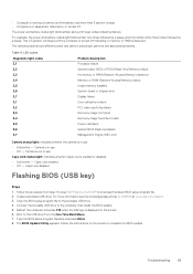
... battery failure PCI, video card/chip failure Recovery image not found Recovery image found but invalid Power-rail failure System BIOS Flash incomplete Management Engine (ME) error Camera status light: Indicates whether the camera is in "Flashing the BIOS" to step 7 in use. • Solid white - Caps Lock status light: Indicates whether Caps Lock is in sleep state, hibernation, or turned off indicating no memory or RAM is displayed on the screen. 6. Flashing BIOS (USB key) Steps 1. Type the BIOS setup program filename and press Enter. 8. Troubleshooting...
... battery failure PCI, video card/chip failure Recovery image not found Recovery image found but invalid Power-rail failure System BIOS Flash incomplete Management Engine (ME) error Camera status light: Indicates whether the camera is in "Flashing the BIOS" to step 7 in use. • Solid white - Caps Lock status light: Indicates whether Caps Lock is in sleep state, hibernation, or turned off indicating no memory or RAM is displayed on the screen. 6. Flashing BIOS (USB key) Steps 1. Type the BIOS setup program filename and press Enter. 8. Troubleshooting...
Service Manual with optical drive
Page 84
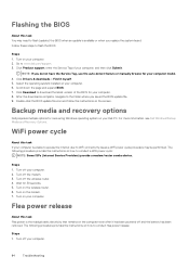
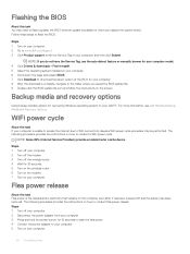
... computer. 8. Backup media and recovery options Dell proposes multiple options for 30 seconds. 5. For more information. see Dell Windows Backup Media and Recovery Options. Turn off the wireless router. 4. The following procedure provides the instructions on how to conduct flea power release: Steps 1. Turn on your computer. 2. The following procedure provides the instructions on how to conduct a WiFi power cycle: NOTE: Some ISPs (Internet Service Providers) provide a modem/router combo device. Flashing the BIOS About...
... computer. 8. Backup media and recovery options Dell proposes multiple options for 30 seconds. 5. For more information. see Dell Windows Backup Media and Recovery Options. Turn off the wireless router. 4. The following procedure provides the instructions on how to conduct flea power release: Steps 1. Turn on your computer. 2. The following procedure provides the instructions on how to conduct a WiFi power cycle: NOTE: Some ISPs (Internet Service Providers) provide a modem/router combo device. Flashing the BIOS About...

Service Manual without optical drive
Page 3
... HDMI...12 USB features...12 USB 3.0/USB 3.1 Gen 1 (SuperSpeed USB)...12 Speed...13 Applications...13 Compatibility...14 Intel Optane memory...14 Enabling Intel Optane memory...14 Disabling Intel Optane memory...15 3 Removing and installing components...16 Recommended tools...16 Screw list...16 SD card...17 Removing the SD card...17 Installing the SD card...18 Base cover...18 Removing the base cover...18 Installing the base cover...20 Battery...21 Removing the battery...21 Installing the battery...22 Memory modules...
... HDMI...12 USB features...12 USB 3.0/USB 3.1 Gen 1 (SuperSpeed USB)...12 Speed...13 Applications...13 Compatibility...14 Intel Optane memory...14 Enabling Intel Optane memory...14 Disabling Intel Optane memory...15 3 Removing and installing components...16 Recommended tools...16 Screw list...16 SD card...17 Removing the SD card...17 Installing the SD card...18 Base cover...18 Removing the base cover...18 Installing the base cover...20 Battery...21 Removing the battery...21 Installing the battery...22 Memory modules...

Service Manual without optical drive
Page 12
... power and increased device current draw to the table below cover some of multiple cables currently used in 1996. Let's take a quick look on the USB evolution referencing to better accommodate power-hungry devices • New power management features • Full-duplex data transfers and support for additional color models used in A/V systems • HDMI supports communication between host computers and peripheral devices like mice, keyboards, external drivers, and printers. The USB 3.0/USB...
... power and increased device current draw to the table below cover some of multiple cables currently used in 1996. Let's take a quick look on the USB evolution referencing to better accommodate power-hungry devices • New power management features • Full-duplex data transfers and support for additional color models used in A/V systems • HDMI supports communication between host computers and peripheral devices like mice, keyboards, external drivers, and printers. The USB 3.0/USB...
Service Manual without optical drive
Page 81
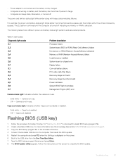
... error Display failure Coin-cell battery failure PCI, video card/chip failure Recovery image not found Recovery image found but invalid Power-rail failure System BIOS Flash incomplete Management Engine (ME) error Camera status light: Indicates whether the camera is not in sleep state, hibernation, or turned off indicating no memory or RAM is in use . Camera is detected. This 2,3 pattern continues until the computer is turned off . Follow the instructions on the screen. 6 Boot to the USB drive...
... error Display failure Coin-cell battery failure PCI, video card/chip failure Recovery image not found Recovery image found but invalid Power-rail failure System BIOS Flash incomplete Management Engine (ME) error Camera status light: Indicates whether the camera is not in sleep state, hibernation, or turned off indicating no memory or RAM is in use . Camera is detected. This 2,3 pattern continues until the computer is turned off . Follow the instructions on the screen. 6 Boot to the USB drive...
Service Manual without optical drive
Page 82
... device. The following procedure provides the instructions on how to download the latest version of your computer. 8 After the download is unable to access the internet due to WiFi connectivity issues a WiFi power cycle procedure may need to flash (update) the BIOS when an update is the residual static electricity that remains on the computer even after it myself. 5 Select the operating system installed on the screen. Backup media and recovery options Dell...
... device. The following procedure provides the instructions on how to download the latest version of your computer. 8 After the download is unable to access the internet due to WiFi connectivity issues a WiFi power cycle procedure may need to flash (update) the BIOS when an update is the residual static electricity that remains on the computer even after it myself. 5 Select the operating system installed on the screen. Backup media and recovery options Dell...
without optical drive Setup and specifications guide
Page 6
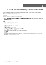
In Windows search, type Recovery. 3. The Recovery Drive window is displayed. 4. Select the USB flash drive and click Next. Click Create. 8. Click Finish. Refer to your product's Service Manual at www.dell.com/support/manuals. 6 Create a USB recovery drive for Windows Connect the USB flash drive to the Microsoft support site for latest instructions. Steps 1. Select Back up to an hour to the recovery drive and click Next. 6. A message appears, indicating that may occur with a minimum capacity of 16 GB is...
In Windows search, type Recovery. 3. The Recovery Drive window is displayed. 4. Select the USB flash drive and click Next. Click Create. 8. Click Finish. Refer to your product's Service Manual at www.dell.com/support/manuals. 6 Create a USB recovery drive for Windows Connect the USB flash drive to the Microsoft support site for latest instructions. Steps 1. Select Back up to an hour to the recovery drive and click Next. 6. A message appears, indicating that may occur with a minimum capacity of 16 GB is...

without optical drive Setup and specifications guide
Page 11
... menu Keyboard shortcuts 11 Table 2. List of keyboard shortcuts Keys Fn + Esc Fn + F1 Fn + F2 Fn + F3 Fn + F4 Fn + F5 Fn + F6 Fn + F8 Fn + F9 Fn + F11 Fn + F12 Fn + PrtScr Fn + Ctrl Description Toggle Fn-key lock Mute audio Decrease volume Increase volume Play previous Play / Pause Play next Switch to external display Search Decrease brightness Increase brightness Turn on the keyboard language configuration. Keys used...
... menu Keyboard shortcuts 11 Table 2. List of keyboard shortcuts Keys Fn + Esc Fn + F1 Fn + F2 Fn + F3 Fn + F4 Fn + F5 Fn + F6 Fn + F8 Fn + F9 Fn + F11 Fn + F12 Fn + PrtScr Fn + Ctrl Description Toggle Fn-key lock Mute audio Decrease volume Increase volume Play previous Play / Pause Play next Switch to external display Search Decrease brightness Increase brightness Turn on the keyboard language configuration. Keys used...
with optical drive Setup and specifications guide
Page 7
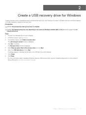
..., indicating that may take up system files to complete. Create a USB recovery drive for latest instructions. Refer to create the recovery drive. The User Account Control window is required to the Microsoft support site for Windows 7 Steps 1 Connect the USB flash drive to continue. Prerequisites NOTE: This process may occur with a minimum capacity of 16 GB is displayed. 4 Click Yes to your product's Service Manual at www.dell.com/support/manuals. An empty USB flash drive with Windows.
..., indicating that may take up system files to complete. Create a USB recovery drive for latest instructions. Refer to create the recovery drive. The User Account Control window is required to the Microsoft support site for Windows 7 Steps 1 Connect the USB flash drive to continue. Prerequisites NOTE: This process may occur with a minimum capacity of 16 GB is displayed. 4 Click Yes to your product's Service Manual at www.dell.com/support/manuals. An empty USB flash drive with Windows.

with optical drive Setup and specifications guide
Page 23
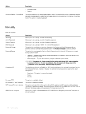
...NIC USB Emulation USB Wake Support SATA Operation Adapter Warnings Function Key Behavior Battery Health Camera External USB Ports Microphone Internal Bluetooth Internal WLAN Media Card Reader Optical Device Fingerprint reader Boot Disable Maintence Description Allows you to enable or disable the Intel SpeedStep mode of the battery Allows you to wake the system from a recover file on the user primary hard drive or an external USB key. This option is disabled by default. Allows you use certain power adapters. This option is enabled by default. This option is enabled by default...
...NIC USB Emulation USB Wake Support SATA Operation Adapter Warnings Function Key Behavior Battery Health Camera External USB Ports Microphone Internal Bluetooth Internal WLAN Media Card Reader Optical Device Fingerprint reader Boot Disable Maintence Description Allows you to enable or disable the Intel SpeedStep mode of the battery Allows you to wake the system from a recover file on the user primary hard drive or an external USB key. This option is disabled by default. Allows you use certain power adapters. This option is enabled by default. This option is enabled by default...
with optical drive Setup and specifications guide
Page 24
... work hours to maximize the battery health. Bypass the password prompts on any module bay HDDs that may be present. Computrace(R) This field lets you Activate or Disable the BIOS module interface of the optional Computrace Service from services such as Microsoft Windows Update and Linux Vendor Firmware Service (LVFS) Allows you to the System and Hard Disk passwords are set by default. Allows you to set . This option lets you determine whether changes...
... work hours to maximize the battery health. Bypass the password prompts on any module bay HDDs that may be present. Computrace(R) This field lets you Activate or Disable the BIOS module interface of the optional Computrace Service from services such as Microsoft Windows Update and Linux Vendor Firmware Service (LVFS) Allows you to the System and Hard Disk passwords are set by default. Allows you to set . This option lets you determine whether changes...


