Owners Manual
Page 3
... Tools...8 Turning Off Your Computer...8 After Working Inside Your Computer 9 2 Removing and Installing Components 10 Removing the Battery...10 Installing the Battery...11 Removing the Optical Drive...11 Installing the Optical Drive...12 Removing the Access Panel...12 Installing the Access Panel......Removing the Palmrest Assembly...18 Installing the Palmrest Assembly...19 Removing the Battery Connector...20 Installing the Battery Connector...20 Removing the Coin-Cell Battery...21 Installing the Coin-cell battery...21 Removing the Optical Drive Connector 22 Installing the Optical Drive ...
... Tools...8 Turning Off Your Computer...8 After Working Inside Your Computer 9 2 Removing and Installing Components 10 Removing the Battery...10 Installing the Battery...11 Removing the Optical Drive...11 Installing the Optical Drive...12 Removing the Access Panel...12 Installing the Access Panel......Removing the Palmrest Assembly...18 Installing the Palmrest Assembly...19 Removing the Battery Connector...20 Installing the Battery Connector...20 Removing the Coin-Cell Battery...21 Installing the Coin-cell battery...21 Removing the Optical Drive Connector 22 Installing the Optical Drive ...

Owners Manual
Page 6
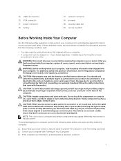
power button 6. speakers 12. camera-status light 5. optical drive 7. touchpad 10. power and battery-status light 11. camera 4. USB 3.0 connector audio connector 6 2. USB 2.0 connector 8. microphone 3. memory-card reader 9. System Overview Front and Back View 1.
power button 6. speakers 12. camera-status light 5. optical drive 7. touchpad 10. power and battery-status light 11. camera 4. USB 3.0 connector audio connector 6 2. USB 2.0 connector 8. microphone 3. memory-card reader 9. System Overview Front and Back View 1.
Owners Manual
Page 7
..., replace all power sources before you connect a cable, ensure that is not authorized by Dell is not covered by your warranty. USB 2.0 connector 15. power connector 19. battery 14. WARNING: Before working inside your computer, read the safety information that shipped with your... before connecting to servicing that both connectors are disconnecting this type of your computer (see the Regulatory Compliance Homepage at www.dell.com/regulatory_compliance CAUTION: Many repairs may appear differently than shown in this document. Hold a card by its pins. As you...
..., replace all power sources before you connect a cable, ensure that is not authorized by Dell is not covered by your warranty. USB 2.0 connector 15. power connector 19. battery 14. WARNING: Before working inside your computer, read the safety information that shipped with your... before connecting to servicing that both connectors are disconnecting this type of your computer (see the Regulatory Compliance Homepage at www.dell.com/regulatory_compliance CAUTION: Many repairs may appear differently than shown in this document. Hold a card by its pins. As you...
Owners Manual
Page 8
... network cables from the electrical outlet before opening the Charms menu and select Settings. Remove the main battery. 8. Open the display. 10. NOTE: To avoid damaging the system board, you must remove the main battery before you turn the computer upside-down on a flat work , periodically touch an unpainted metal surface to...
... network cables from the electrical outlet before opening the Charms menu and select Settings. Remove the main battery. 8. Open the display. 10. NOTE: To avoid damaging the system board, you must remove the main battery before you turn the computer upside-down on a flat work , periodically touch an unpainted metal surface to...
Owners Manual
Page 9
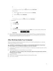
..., ensure you shut down your computer. Using a mouse: and then select Shut down . 1. Do not use only the battery designed for other Dell computers. 1. Replace the battery. 4. Point to the computer, use batteries designed for this particular Dell computer. Click the Or and select Shut down. * On the Home screen, click • In Windows 7: and...
..., ensure you shut down your computer. Using a mouse: and then select Shut down . 1. Do not use only the battery designed for other Dell computers. 1. Replace the battery. 4. Point to the computer, use batteries designed for this particular Dell computer. Click the Or and select Shut down. * On the Home screen, click • In Windows 7: and...

Owners Manual
Page 10
Perform the following steps as shown in Before Working Inside Your Computer. 2. Slide the latches outward [1]. Release the battery [2]. 3. 2 Removing and Installing Components This section provides detailed information on how to remove it from your computer. Follow the procedures in the illustration: a. Lift the battery to remove or install the components from the computer. 10 b. Removing the Battery 1.
Perform the following steps as shown in Before Working Inside Your Computer. 2. Slide the latches outward [1]. Release the battery [2]. 3. 2 Removing and Installing Components This section provides detailed information on how to remove it from your computer. Follow the procedures in the illustration: a. Lift the battery to remove or install the components from the computer. 10 b. Removing the Battery 1.

Owners Manual
Page 11
Installing the Battery 1. Perform the following steps as shown in Before Working Inside Your Computer 2. Remove the screw that secures the optical drive [1]. b. Slide the optical drive out of the computer [2]. 11 Removing the Optical Drive 1. Follow the procedures in the illustration: a. Insert the battery into the battery slot and press to lock in After Working Inside Your computer. Follow the procedures in place. 2. Remove the battery. 3.
Installing the Battery 1. Perform the following steps as shown in Before Working Inside Your Computer 2. Remove the screw that secures the optical drive [1]. b. Slide the optical drive out of the computer [2]. 11 Removing the Optical Drive 1. Follow the procedures in the illustration: a. Insert the battery into the battery slot and press to lock in After Working Inside Your computer. Follow the procedures in place. 2. Remove the battery. 3.

Owners Manual
Page 12
Follow the procedures in After Working Inside Your computer. Remove the Battery. 3. Loosen the screw that secures access panel to secure the optical drive. 3. Lift the access panel off the computer. 12 Follow the procedures in Before Working Inside Your Computer. 2. Slide the access panel from the computer [2]. 4. Slide the optical drive into the computer. 2. b. Removing the Access Panel 1. Install the battery. 4. Installing the Optical Drive 1. Perform the following steps as shown in the illustration: a. Tighten the screw to computer [1].
Follow the procedures in After Working Inside Your computer. Remove the Battery. 3. Loosen the screw that secures access panel to secure the optical drive. 3. Lift the access panel off the computer. 12 Follow the procedures in Before Working Inside Your Computer. 2. Slide the access panel from the computer [2]. 4. Slide the optical drive into the computer. 2. b. Removing the Access Panel 1. Install the battery. 4. Installing the Optical Drive 1. Perform the following steps as shown in the illustration: a. Tighten the screw to computer [1].

Owners Manual
Page 13
... in Before Working Inside Your Computer. 2. Insert the access panel into the chassis. 2. Tighten the screw to secure the access panel to the computer [1]. Install battery. 4. Remove the...
... in Before Working Inside Your Computer. 2. Insert the access panel into the chassis. 2. Tighten the screw to secure the access panel to the computer [1]. Install battery. 4. Remove the...
Owners Manual
Page 14
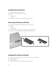
... the system board. Install the access panel. 3. Remove the memory module from the memory module until it to lock the securing clips. 2. Remove: a. battery 4. Tighten the screw to secure it pops up. 4. battery b. Install the battery. 4. access panel 3. Installing the Hard Drive 1. access panel b. Follow the procedures in After Working Inside Your computer.
... the system board. Install the access panel. 3. Remove the memory module from the memory module until it to lock the securing clips. 2. Remove: a. battery 4. Tighten the screw to secure it pops up. 4. battery b. Install the battery. 4. access panel 3. Installing the Hard Drive 1. access panel b. Follow the procedures in After Working Inside Your computer.
Owners Manual
Page 16
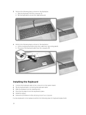
... keyboard to the connector on the system board. 2. Disconnect the keyboard cable from the locking tab [1]. Slide the keyboard into the retaining slots. 4. Install the battery. 6. If a new keyboard is to lock the keyboard in the illustration: a. Connect the keyboard cable to access the cable below [2]. 4. b. Flip the keyboard after connecting...
... keyboard to the connector on the system board. 2. Disconnect the keyboard cable from the locking tab [1]. Slide the keyboard into the retaining slots. 4. Install the battery. 6. If a new keyboard is to lock the keyboard in the illustration: a. Connect the keyboard cable to access the cable below [2]. 4. b. Flip the keyboard after connecting...
Owners Manual
Page 18
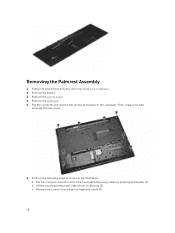
Then, release the tabs securing the base cover. 6. Lift the touchpad and power cables from inside the keyboard cavity [3]. 18 Flip the computer and remove the screws at the base of the computer. Flip the computer and disconnect the touchpad and power cables by pressing locking tab [1]. Remove the screws from locking tab [2]. Perform the following steps as shown in Before Working Inside Your Computer. 2. b. Removing the Palmrest Assembly 1. Remove the keyboard. 5. Remove the Battery. 3. c. Follow the procedures in the illustration: a. Remove the access panel. 4.
Then, release the tabs securing the base cover. 6. Lift the touchpad and power cables from inside the keyboard cavity [3]. 18 Flip the computer and remove the screws at the base of the computer. Flip the computer and disconnect the touchpad and power cables by pressing locking tab [1]. Remove the screws from locking tab [2]. Perform the following steps as shown in Before Working Inside Your Computer. 2. b. Removing the Palmrest Assembly 1. Remove the keyboard. 5. Remove the Battery. 3. c. Follow the procedures in the illustration: a. Remove the access panel. 4.
Owners Manual
Page 20
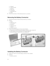
... 3. Remove the screws that secure the battery connector to a 45-degree angle [2]. Lift the battery connector partially to the computer [1]. c. Install the: a. Removing the Battery Connector 1. Remove the battery connector from the computer [3]. palmrest assembly 20 hard drive e. Installing the Battery Connector 1. WLAN card e. Battery b. Tighten the screws to secure the battery connector to the computer. 2. access...
... 3. Remove the screws that secure the battery connector to a 45-degree angle [2]. Lift the battery connector partially to the computer [1]. c. Install the: a. Removing the Battery Connector 1. Remove the battery connector from the computer [3]. palmrest assembly 20 hard drive e. Installing the Battery Connector 1. WLAN card e. Battery b. Tighten the screws to secure the battery connector to the computer. 2. access...
Owners Manual
Page 21
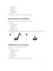
... Follow the procedures in After Working Inside Your computer. 21 Battery b. Install: a. palmrest assembly b. memory module d. battery 3. WLAN card f. battery 3. hard drive e. memory module f. palmrest assembly 3. memory module d. access panel d. Installing the Coin-cell battery 1. Insert the coin-cell battery and press to remove it from the computer. keyboard c. hard... Inside Your computer. WLAN card f. Push the coin-cell release latch using a scribe and then pull the coin-cell battery to lock. 2. optical disk-drive h. keyboard c. Removing the Coin-Cell...
... Follow the procedures in After Working Inside Your computer. 21 Battery b. Install: a. palmrest assembly b. memory module d. battery 3. WLAN card f. battery 3. hard drive e. memory module f. palmrest assembly 3. memory module d. access panel d. Installing the Coin-cell battery 1. Insert the coin-cell battery and press to remove it from the computer. keyboard c. hard... Inside Your computer. WLAN card f. Push the coin-cell release latch using a scribe and then pull the coin-cell battery to lock. 2. optical disk-drive h. keyboard c. Removing the Coin-Cell...
Owners Manual
Page 22
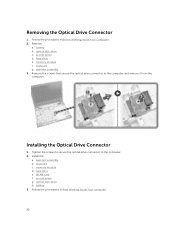
... panel d. memory module f. memory module d. Follow the procedures in Before Working Inside Your Computer. 2. Removing the Optical Drive Connector 1. keyboard g. battery 3. Install the: a. palmrest assembly 3. WLAN card f. Installing the Optical Drive Connector 1. Tighten the screws to secure the optical drive connector to the computer and remove ...
... panel d. memory module f. memory module d. Follow the procedures in Before Working Inside Your Computer. 2. Removing the Optical Drive Connector 1. keyboard g. battery 3. Install the: a. palmrest assembly 3. WLAN card f. Installing the Optical Drive Connector 1. Tighten the screws to secure the optical drive connector to the computer and remove ...
Owners Manual
Page 23
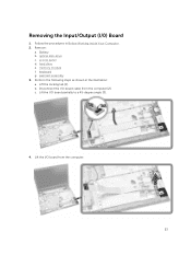
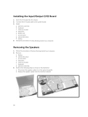
Remove: a. Battery b. access panel d. memory module f. Lift the locking tab [1]. b. Lift the I /0) Board 1. optical disk-drive c. Lift the I /O board cable from the computer. 23 Follow the procedures in the illustration: a. hard drive e. keyboard g. c. Perform the following steps as shown in Before Working Inside Your Computer. 2. Disconnect the I /O board from the computer [2]. palmrest assembly 3. Removing the Input/Output (I /O board partially to a 45-degree angle [3]. 4.
Remove: a. Battery b. access panel d. memory module f. Lift the locking tab [1]. b. Lift the I /0) Board 1. optical disk-drive c. Lift the I /O board cable from the computer. 23 Follow the procedures in the illustration: a. hard drive e. keyboard g. c. Perform the following steps as shown in Before Working Inside Your Computer. 2. Disconnect the I /O board from the computer [2]. palmrest assembly 3. Removing the Input/Output (I /O board partially to a 45-degree angle [3]. 4.
Owners Manual
Page 24
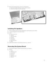
... b. memory module d. optical disk-drive h. Removing the Speakers 1. c. access panel. palmrest assembly. 3. keyboard c. keyboard. Disconnect the speaker cables from the retention tabs [2]. 24 WLAN card f. battery 4. Battery. Perform the following steps as shown in After Working Inside Your computer. Install: a. access panel g. Follow the procedures in the illustration: a. optical disk-drive. hard...
... b. memory module d. optical disk-drive h. Removing the Speakers 1. c. access panel. palmrest assembly. 3. keyboard c. keyboard. Disconnect the speaker cables from the retention tabs [2]. 24 WLAN card f. battery 4. Battery. Perform the following steps as shown in After Working Inside Your computer. Install: a. access panel g. Follow the procedures in the illustration: a. optical disk-drive. hard...
Owners Manual
Page 25
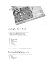
... illustration: a. c. WLAN card. f. palmrest assembly b. keyboard c. Follow the procedures in Before Working Inside Your Computer. 2. Removing the System Board 1. Battery. hard drive. 4. b. Remove the speakers from the retention clips [1]. Install: a. hard drive e. keyboard. 25 Installing the Speakers 1. Follow the procedures...system board. 3. WLAN card f. access panel g. b. access panel. memory module d. optical disk-drive h. Remove: a. battery 4. e. optical disk-drive. d. Perform the following steps as shown in place. 2. memory module.
... illustration: a. c. WLAN card. f. palmrest assembly b. keyboard c. Follow the procedures in Before Working Inside Your Computer. 2. Removing the System Board 1. Battery. hard drive. 4. b. Remove the speakers from the retention clips [1]. Install: a. hard drive e. keyboard. 25 Installing the Speakers 1. Follow the procedures...system board. 3. WLAN card f. access panel g. b. access panel. memory module d. optical disk-drive h. Remove: a. battery 4. e. optical disk-drive. d. Perform the following steps as shown in place. 2. memory module.
Owners Manual
Page 27
... h. access panel 27 Tighten the screws to secure the system board to the computer. 7. memory module d. Follow the procedures in After Working Inside Your computer. Battery b. Install: a. battery 8. optical disk-drive c. Insert the system board into the chassis. 2.
... h. access panel 27 Tighten the screws to secure the system board to the computer. 7. memory module d. Follow the procedures in After Working Inside Your computer. Battery b. Install: a. battery 8. optical disk-drive c. Insert the system board into the chassis. 2.
Owners Manual
Page 30
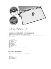
...in the display bezel to the display assembly. 3. keyboard d. system board b. optical disk-drive h. access panel 30 hard drive f. optical disk-drive c. Battery b. Tighten the screws to secure the display panel to the display assembly. 5. Install: a. Follow the procedures in After Working Inside Your computer. access panel ...WLAN cables through their tabs and then tighten the display hinge screws to secure the display assembly. 6. palmrest assembly c. memory module e. battery 7. Follow the procedures in Before Working Inside Your Computer. 2. Remove: a.
...in the display bezel to the display assembly. 3. keyboard d. system board b. optical disk-drive h. access panel 30 hard drive f. optical disk-drive c. Battery b. Tighten the screws to secure the display panel to the display assembly. 5. Install: a. Follow the procedures in After Working Inside Your computer. access panel ...WLAN cables through their tabs and then tighten the display hinge screws to secure the display assembly. 6. palmrest assembly c. memory module e. battery 7. Follow the procedures in Before Working Inside Your Computer. 2. Remove: a.

