
Owners Manual
Page 3
.... As you finish working inside the computer, replace all power sources before you connect a cable, ensure that is not authorized by Dell is not covered by its pull-tab, not on the cable itself. After you pull connectors apart, keep them evenly aligned to the power source. You should only perform troubleshooting and simple repairs as directed by performing the removal procedure in this...
.... As you finish working inside the computer, replace all power sources before you connect a cable, ensure that is not authorized by Dell is not covered by its pull-tab, not on the cable itself. After you pull connectors apart, keep them evenly aligned to the power source. You should only perform troubleshooting and simple repairs as directed by performing the removal procedure in this...
Owners Manual
Page 4
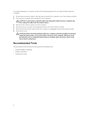
... all network cables from being scratched. 2. While you begin working inside your computer, ground yourself by touching an unpainted metal surface, such as the metal at the back of the computer. Turn off your work , periodically touch an unpainted metal surface to dissipate static electricity, which could harm internal components. Disconnect all attached devices from the network device. 3. Remove the cover. Recommended...
... all network cables from being scratched. 2. While you begin working inside your computer, ground yourself by touching an unpainted metal surface, such as the metal at the back of the computer. Turn off your work , periodically touch an unpainted metal surface to dissipate static electricity, which could harm internal components. Disconnect all attached devices from the network device. 3. Remove the cover. Recommended...

Owners Manual
Page 5
... computer works correctly by running the Dell Diagnostics. 5 If your computer and attached devices did not automatically turn off when you turn them off . Connect any external devices, cards, and cables before you shut down the operating system: • In Windows 8: - b. or 1. Click the arrow in from the right edge of the screen, opening the Charms menu and select Settings. After Working Inside Your Computer After you complete any replacement procedure...
... computer works correctly by running the Dell Diagnostics. 5 If your computer and attached devices did not automatically turn off when you turn them off . Connect any external devices, cards, and cables before you shut down the operating system: • In Windows 8: - b. or 1. Click the arrow in from the right edge of the screen, opening the Charms menu and select Settings. After Working Inside Your Computer After you complete any replacement procedure...
Owners Manual
Page 15
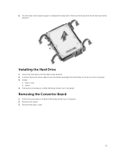
Pry the hard-drive bracket apart to its slot on the computer. 3. Install: a. Follow the procedures in Before Working Inside Your Computer. 2. Follow the procedures in After Working Inside Your Computer. Insert the hard drive into the hard-drive bracket. 2. back cover b. Remove the stand. 3. Remove the back cover. 15 Remove the hard drive from the hard-drive bracket. Installing the Hard Drive 1. Connect the hard-drive cable to the hard drive and align the hard drive to release the hard drive. stand 4. Removing the Convertor Board 1. 6.
Pry the hard-drive bracket apart to its slot on the computer. 3. Install: a. Follow the procedures in Before Working Inside Your Computer. 2. Follow the procedures in After Working Inside Your Computer. Insert the hard drive into the hard-drive bracket. 2. back cover b. Remove the stand. 3. Remove the back cover. 15 Remove the hard drive from the hard-drive bracket. Installing the Hard Drive 1. Connect the hard-drive cable to the hard drive and align the hard drive to release the hard drive. stand 4. Removing the Convertor Board 1. 6.
Owners Manual
Page 16
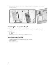
Disconnect the cables from the computer. Connect the cables to the computer. Tighten the screws to secure the convertor board to the convertor board. 2. Install: a. stand 3. Follow the procedures in Before Working Inside Your Computer. 2. Remove the stand. 3. Removing the Memory 1. Follow the procedures in After Working Inside Your Computer. back cover b. Installing the Convertor Board 1. Remove the screws and lift the convertor board from the convertor board. 4. Remove the back cover. 16
Disconnect the cables from the computer. Connect the cables to the computer. Tighten the screws to secure the convertor board to the convertor board. 2. Install: a. stand 3. Follow the procedures in Before Working Inside Your Computer. 2. Remove the stand. 3. Removing the Memory 1. Follow the procedures in After Working Inside Your Computer. back cover b. Installing the Convertor Board 1. Remove the screws and lift the convertor board from the convertor board. 4. Remove the back cover. 16
Owners Manual
Page 17
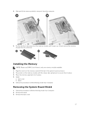
... its connector. Press down on the memory-card with the tab in After Working Inside Your Computer. Follow the procedures in place. 3. Removing the System-Board Shield 1. Lift and remove the memory module from the computer. 5. Pry the retention clips away from the memory module until the release tabs spring back to remove it pops-up. Installing the Memory NOTE: Please use DIMM 2 slot if...
... its connector. Press down on the memory-card with the tab in After Working Inside Your Computer. Follow the procedures in place. 3. Removing the System-Board Shield 1. Lift and remove the memory module from the computer. 5. Pry the retention clips away from the memory module until the release tabs spring back to remove it pops-up. Installing the Memory NOTE: Please use DIMM 2 slot if...
Owners Manual
Page 19
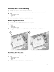
... heatsink on the system board. 2. Installing the Heatsink 1. system-board shield b. back cover c. Install: a. system-board shield b. Removing the Heatsink 1. Follow the procedures in After Working Inside Your Computer. 19 back cover c. Lift and remove the heatsink from the computer. Tighten the screws to the computer. Follow the procedures in Before Working Inside Your Computer. 2. Press the coin cell battery downward until the release...
... heatsink on the system board. 2. Installing the Heatsink 1. system-board shield b. back cover c. Install: a. system-board shield b. Removing the Heatsink 1. Follow the procedures in After Working Inside Your Computer. 19 back cover c. Lift and remove the heatsink from the computer. Tighten the screws to the computer. Follow the procedures in Before Working Inside Your Computer. 2. Press the coin cell battery downward until the release...
Owners Manual
Page 21
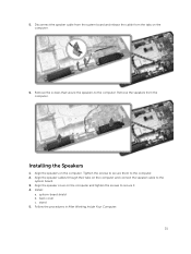
... system board. 3. back cover c. Installing the Speakers 1. Align the speaker cover on the computer and connect the speaker cable to secure it. 4. Remove the speakers from the tabs on the computer. Follow the procedures in After Working Inside Your Computer. 21 Align the speakers on the computer. 6. Disconnect the speaker cable from the system board and release the cable from the computer. Remove the screws that secure the speakers to...
... system board. 3. back cover c. Installing the Speakers 1. Align the speaker cover on the computer and connect the speaker cable to secure it. 4. Remove the speakers from the tabs on the computer. Follow the procedures in After Working Inside Your Computer. 21 Align the speakers on the computer. 6. Disconnect the speaker cable from the system board and release the cable from the computer. Remove the screws that secure the speakers to...
Owners Manual
Page 24
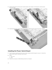
3. Lift the power-switch board to secure it from the computer. Insert the power-switch board into its slot on the computer and fix the tape to access the cable. 4. Installing the Power-Switch Board 1. stand 3. Connect the power-switch cable to remove it . back cover b. Follow the procedures in After Working Inside Your Computer. 24 Disconnect the power-switch cable from the power-switch board to the power-switch board. 2. Install: a. Peel the tape that secures the power-switch board to the computer.
3. Lift the power-switch board to secure it from the computer. Insert the power-switch board into its slot on the computer and fix the tape to access the cable. 4. Installing the Power-Switch Board 1. stand 3. Connect the power-switch cable to remove it . back cover b. Follow the procedures in After Working Inside Your Computer. 24 Disconnect the power-switch cable from the power-switch board to the power-switch board. 2. Install: a. Peel the tape that secures the power-switch board to the computer.
Owners Manual
Page 26
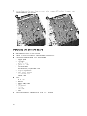
...Align the system board on the computer. 2. camera cable b. VESA bracket e. system fan cable d. convertor-board cable h. Install: a. back cover g. Lift to the system board: a. LVDS cable c. hard-drive/optical-drive power cable g. speaker cable 4. hard-drive cable f. system-board shield d. power-switch cable j. heatsink c. touch cable (if available) i. memory f. Connect the following cables to release the system board and remove it from the computer. optical-drive cable e. WLAN card b. Follow the procedures in After Working Inside Your Computer. 26...
...Align the system board on the computer. 2. camera cable b. VESA bracket e. system fan cable d. convertor-board cable h. Install: a. back cover g. Lift to the system board: a. LVDS cable c. hard-drive/optical-drive power cable g. speaker cable 4. hard-drive cable f. system-board shield d. power-switch cable j. heatsink c. touch cable (if available) i. memory f. Connect the following cables to release the system board and remove it from the computer. optical-drive cable e. WLAN card b. Follow the procedures in After Working Inside Your Computer. 26...
Owners Manual
Page 28
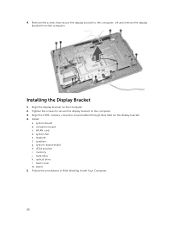
Installing the Display Bracket 1. Install: a. system fan e. hard drive k. Follow the procedures in After Working Inside Your Computer. 28 convertor board c. speakers g. Lift and remove the display bracket from the computer. Align the LVDS, camera, convertor-board cables through their tabs on the computer. 2. WLAN card d. back cover m. Align the display bracket on the display bracket. 4. stand 5. system-board shield h. VESA bracket i. system board b. optical drive l. 4. Remove the screws that secure the display bracket to...
Installing the Display Bracket 1. Install: a. system fan e. hard drive k. Follow the procedures in After Working Inside Your Computer. 28 convertor board c. speakers g. Lift and remove the display bracket from the computer. Align the LVDS, camera, convertor-board cables through their tabs on the computer. 2. WLAN card d. back cover m. Align the display bracket on the display bracket. 4. stand 5. system-board shield h. VESA bracket i. system board b. optical drive l. 4. Remove the screws that secure the display bracket to...
Owners Manual
Page 30
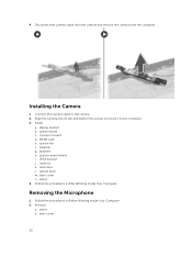
... card e. speakers h. VESA bracket j. memory k. Disconnect the camera cable from the camera and remove the camera from the computer. convertor board d. system-board shield i. stand 4. Remove: a. stand b. Align the camera into its slot and tighten the screws to secure it to the camera. 2. system fan f. hard drive l. Follow the procedures in Before Working Inside Your Computer. 2. Follow the procedures in After Working Inside Your Computer. back cover n. Install: a. Connect...
... card e. speakers h. VESA bracket j. memory k. Disconnect the camera cable from the camera and remove the camera from the computer. convertor board d. system-board shield i. stand 4. Remove: a. stand b. Align the camera into its slot and tighten the screws to secure it to the camera. 2. system fan f. hard drive l. Follow the procedures in Before Working Inside Your Computer. 2. Follow the procedures in After Working Inside Your Computer. back cover n. Install: a. Connect...
Owners Manual
Page 31
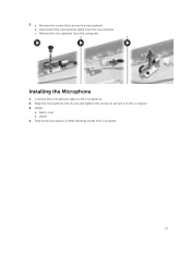
b. Disconnect the microphone cable from the computer. Install: a. back cover b. stand 4. a. Installing the Microphone 1. 3. Remove the microphone from the microphone. Align the microphone into its slot and tighten the screws to secure it to the microphone. 2. c. Connect the microphone cable to the computer. 3. Remove the screw that secures the microphone. Follow the procedures in After Working Inside Your Computer. 31
b. Disconnect the microphone cable from the computer. Install: a. back cover b. stand 4. a. Installing the Microphone 1. 3. Remove the microphone from the microphone. Align the microphone into its slot and tighten the screws to secure it to the microphone. 2. c. Connect the microphone cable to the computer. 3. Remove the screw that secures the microphone. Follow the procedures in After Working Inside Your Computer. 31

Owners Manual
Page 32
... boot menu by pressing key The one-time boot menu displays the devices that you make are : • Removable Drive (if available) • STXXXX Drive NOTE: XXX denotes the SATA drive number. • Optical Drive • Diagnostics NOTE: Choosing Diagnostics, will display the ePSA diagnostics screen. NOTE: For most of the system setup options, changes that you can : • Change the NVRAM settings after you add or remove hardware • View the system hardware configuration • Enable or disable integrated devices • Set performance and power management...
... boot menu by pressing key The one-time boot menu displays the devices that you make are : • Removable Drive (if available) • STXXXX Drive NOTE: XXX denotes the SATA drive number. • Optical Drive • Diagnostics NOTE: Choosing Diagnostics, will display the ePSA diagnostics screen. NOTE: For most of the system setup options, changes that you can : • Change the NVRAM settings after you add or remove hardware • View the system hardware configuration • Enable or disable integrated devices • Set performance and power management...

Owners Manual
Page 34
...Core Support Default: Enabled USB Configuration USB 3.0 Port Compatibility Rear USB Ports Side USB Ports Allows you to select the SATA operation mode Default: Enabled Default: AHCI 34 Default: USB 2.0 Default: Enabled Default: Enabled Onboard Device Configuration Onboard Audio Controller SATA Mode Enable or disable the onboard audio controller Allows you to set various functions that affect the performance of the hard drive. Displays the model number and capacity of each option and its default value. Memory Installed Memory Available System Memory Speed Memory Technology SATA...
...Core Support Default: Enabled USB Configuration USB 3.0 Port Compatibility Rear USB Ports Side USB Ports Allows you to select the SATA operation mode Default: Enabled Default: AHCI 34 Default: USB 2.0 Default: Enabled Default: Enabled Onboard Device Configuration Onboard Audio Controller SATA Mode Enable or disable the onboard audio controller Allows you to set various functions that affect the performance of the hard drive. Displays the model number and capacity of each option and its default value. Memory Installed Memory Available System Memory Speed Memory Technology SATA...

Owners Manual
Page 35
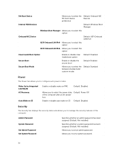
...Default: Internal ODD Devices Allows you to change the boot sequence. Onboard LAN Controller Onboard LAN Boot ROM Enable or disable the onboard LAN controller Enable or disable the onboard LAN boot ROM Default: Enabled Default: Disabled AC Power Adapter Detection Enable or disable the AC power adapter detection Default: Enabled Boot The Boot tab allows you to select the 4th boot device preference Default: USB Floppy Devices 35 Numlock Key Keyboard Errors USB Boot Support Boot Meu Security Load Legacy OPROM Boot Mode 1st Boot Device 2nd Boot Device 3rd Boot Device 4th Boot Device...
...Default: Internal ODD Devices Allows you to change the boot sequence. Onboard LAN Controller Onboard LAN Boot ROM Enable or disable the onboard LAN controller Enable or disable the onboard LAN boot ROM Default: Enabled Default: Disabled AC Power Adapter Detection Enable or disable the AC power adapter detection Default: Enabled Boot The Boot tab allows you to select the 4th boot device preference Default: USB Floppy Devices 35 Numlock Key Keyboard Errors USB Boot Support Boot Meu Security Load Legacy OPROM Boot Mode 1st Boot Device 2nd Boot Device 3rd Boot Device 4th Boot Device...
Owners Manual
Page 36
... Devices Internal HDD Devices Default: Windows Boot Manager Windows Boot Manager Allows you to select this option Onboard NIC Device Default: UEFI Onboard LAN IPv4 UEFI Onboard LAN IPv4 Allows you to select this option UEFI Onboard LAN IPv6 Allows you to select this option Clear Invalid Boot Option Enable or disable clear Default: Disabled invalid boot option Secure Boot Enable or disable the secure boot Default: Enabled Secure Boot Mode Allows you to select the between standard and custom modes Default: Standard Power The Power tab allows you to set a system password...
... Devices Internal HDD Devices Default: Windows Boot Manager Windows Boot Manager Allows you to select this option Onboard NIC Device Default: UEFI Onboard LAN IPv4 UEFI Onboard LAN IPv4 Allows you to select this option UEFI Onboard LAN IPv6 Allows you to select this option Clear Invalid Boot Option Enable or disable clear Default: Disabled invalid boot option Secure Boot Enable or disable the secure boot Default: Enabled Secure Boot Mode Allows you to select the between standard and custom modes Default: Standard Power The Power tab allows you to set a system password...

Owners Manual
Page 37
... replacing the system board or if an update is fully charged and connected to a power outlet 1. Click Run to install the updated BIOS settings on your BIOS (system setup), on your computer. 12. HDD Password Setting Password Change Password Bypass HDD Protection Allows you to select the hard drive that your download method below window; NOTE: To locate the Service Tag, click Where is recommended to dell.com/support. 3. Click Get drivers and click View All Drivers. The File Download window...
... replacing the system board or if an update is fully charged and connected to a power outlet 1. Click Run to install the updated BIOS settings on your BIOS (system setup), on your computer. 12. HDD Password Setting Password Change Password Bypass HDD Protection Allows you to select the hard drive that your download method below window; NOTE: To locate the Service Tag, click Where is recommended to dell.com/support. 3. Click Get drivers and click View All Drivers. The File Download window...
Owners Manual
Page 41
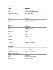
Displays Feature Type Maximum resolution Refresh rate Brightness Operating angle Pixel pitch Controls Dimensions: Height Width Diagonal Table 8. Table 5. Drives Feature Hard drive Optical drive (optional) Table 9. Ports and Connectors Feature Audio Network adapter Specification ALC3661-CG (Realtek) single 4-ohms, 2.5 W AVG speakers up to 3 W per channel single digital microphone (optional) Specification Intel 10/100/1000 Mbps Ethernet LAN half mini-card (Wi-Fi b/g/n supporting Wi-Fi display) (optional) Specification 19.5 inch HD+ WLED 1600 x 900 60 Hz...
Displays Feature Type Maximum resolution Refresh rate Brightness Operating angle Pixel pitch Controls Dimensions: Height Width Diagonal Table 8. Table 5. Drives Feature Hard drive Optical drive (optional) Table 9. Ports and Connectors Feature Audio Network adapter Specification ALC3661-CG (Realtek) single 4-ohms, 2.5 W AVG speakers up to 3 W per channel single digital microphone (optional) Specification Intel 10/100/1000 Mbps Ethernet LAN half mini-card (Wi-Fi b/g/n supporting Wi-Fi display) (optional) Specification 19.5 inch HD+ WLED 1600 x 900 60 Hz...

Owners Manual
Page 43
...Solid white light indicates power-on integrated network adapter Power supply diagnostic light Specification White light - Orange - Green light - White light - Green- The power supply is turned on and is without an optical disk drive. The above weight is functional. Table 14. White light - solid while light indicates that the camera is not detecting a physical connection to the network. Yellow light - Controls and Lights Feature Power button light Hard Drive activity light Camera LED Back panel: Link integrity light on integrated network adapter : Network activity light on...
...Solid white light indicates power-on integrated network adapter Power supply diagnostic light Specification White light - Orange - Green light - White light - Green- The power supply is turned on and is without an optical disk drive. The above weight is functional. Table 14. White light - solid while light indicates that the camera is not detecting a physical connection to the network. Yellow light - Controls and Lights Feature Power button light Hard Drive activity light Camera LED Back panel: Link integrity light on integrated network adapter : Network activity light on...


