
User Manual
Page 1
... (2) 6. optical drive 7. touchpad buttons (2) 13. Front And Back View Figure 1. speakers (2) 5. optical drive eject button 8. touchpad 11. device status lights 14. Vostro 2420 - Front View 1. microphone 10. keyboard 15. Dell Vostro 2420/2520 Setup And Features Information About Warnings WARNING: A WARNING indicates a potential for property damage, personal injury, or death. power button Regulatory Model: P22G...
... (2) 6. optical drive 7. touchpad buttons (2) 13. Front And Back View Figure 1. speakers (2) 5. optical drive eject button 8. touchpad 11. device status lights 14. Vostro 2420 - Front View 1. microphone 10. keyboard 15. Dell Vostro 2420/2520 Setup And Features Information About Warnings WARNING: A WARNING indicates a potential for property damage, personal injury, or death. power button Regulatory Model: P22G...

User Manual
Page 3
optical drive 6. memory card reader 12. Vostro 2520 - camera status light 2. device status lights 13. keyboard 14. Front View 1. touchpad 9. Front And Back View Figure 3. optical drive eject button 7. microphone 11. touchpad buttons (2) 10. camera 3. power button 3 display 4. speakers (2) 5. USB 2.0 connectors (2) 8.
optical drive 6. memory card reader 12. Vostro 2520 - camera status light 2. device status lights 13. keyboard 14. Front View 1. touchpad 9. Front And Back View Figure 3. optical drive eject button 7. microphone 11. touchpad buttons (2) 10. camera 3. power button 3 display 4. speakers (2) 5. USB 2.0 connectors (2) 8.

User Manual
Page 5
... USB Connector 4. Specifications NOTE: Offerings may vary by law to a docking device or other external device, such as a mouse or keyboard (optional). AC Adapter 2. Power Button NOTE: It is recommended that you turn on and shut down your computer at least once before ...configuration of your computer, click Start → Help and Support and select the option to turn on the computer. Power AC adapter Vostro 2420 / Vostro 2520 with your computer. Connect the network cable (optional). Open the computer display and press the power button to view information about your computer...
... USB Connector 4. Specifications NOTE: Offerings may vary by law to a docking device or other external device, such as a mouse or keyboard (optional). AC Adapter 2. Power Button NOTE: It is recommended that you turn on and shut down your computer at least once before ...configuration of your computer, click Start → Help and Support and select the option to turn on the computer. Power AC adapter Vostro 2420 / Vostro 2520 with your computer. Connect the network cable (optional). Open the computer display and press the power button to view information about your computer...
Owner's Manual
Page 3
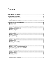
... Digital (SD) Card...10 Installing the Secure Digital (SD) Card...10 Removing the Hinge Cover...10 Installing the Hinge Cover...11 Removing the Keyboard...11 Installing the Keyboard...13 Removing the Optical Drive...13 Installing the Optical Drive...14 Removing the Memory Module...14 Installing the Memory Module...15 Removing the Palmrest...
... Digital (SD) Card...10 Installing the Secure Digital (SD) Card...10 Removing the Hinge Cover...10 Installing the Hinge Cover...11 Removing the Keyboard...11 Installing the Keyboard...13 Removing the Optical Drive...13 Installing the Optical Drive...14 Removing the Memory Module...14 Installing the Memory Module...15 Removing the Palmrest...

Owner's Manual
Page 11
Flip the computer and remove the hinge cover. Install the hinge cover and press on it to secure it to the computer. 11 Remove the battery. 3. Install the battery. 4. Pry up to release the tabs securing the keyboard to the computer. 2. Flip the computer and install the screw that secures the hinge cover. 3. Follow the procedures in Before Working Inside Your Computer. 2. 4. Follow the procedures in After Working Inside Your Computer. Installing the Hinge Cover 1. Removing the Keyboard 1.
Flip the computer and remove the hinge cover. Install the hinge cover and press on it to secure it to the computer. 11 Remove the battery. 3. Install the battery. 4. Pry up to release the tabs securing the keyboard to the computer. 2. Flip the computer and install the screw that secures the hinge cover. 3. Follow the procedures in Before Working Inside Your Computer. 2. 4. Follow the procedures in After Working Inside Your Computer. Installing the Hinge Cover 1. Removing the Keyboard 1.

Owner's Manual
Page 12
Flip the keyboard and lay it on the palmrest. 5. Disconnect the keyboard cable from the computer. 12 Remove the keyboard from the system board. 6. 4.
Flip the keyboard and lay it on the palmrest. 5. Disconnect the keyboard cable from the computer. 12 Remove the keyboard from the system board. 6. 4.

Owner's Manual
Page 13
Remove the battery. 3. Installing the Keyboard 1. Install the battery. 5. Follow the procedures in After Working Inside Your Computer. Remove the keyboard. 4. Slide the optical drive out of 30 degrees to the system board. 2. Insert the keyboard at an angle of the computer. 13 Connect the keyboard cable to its compartment. 3. Follow the procedures in Before Working Inside Your Computer. 2. Removing the Optical Drive 1. Remove the screw that secures the optical drive. 5. Press down on the keyboard until it clicks into place. 4.
Remove the battery. 3. Installing the Keyboard 1. Install the battery. 5. Follow the procedures in After Working Inside Your Computer. Remove the keyboard. 4. Slide the optical drive out of 30 degrees to the system board. 2. Insert the keyboard at an angle of the computer. 13 Connect the keyboard cable to its compartment. 3. Follow the procedures in Before Working Inside Your Computer. 2. Removing the Optical Drive 1. Remove the screw that secures the optical drive. 5. Press down on the keyboard until it clicks into place. 4.
Owner's Manual
Page 14
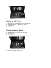
Removing the Memory Module 1. Pry the retention clips away from the computer. 14 Remove the memory module from the memory module until it pops up. 5. Installing the Optical Drive 1. Remove the battery. 3. Tighten the screw to secure the optical drive to the computer. 3. Install the battery. 5. Install the keyboard. 4. Follow the procedures in After Working Inside Your Computer. Slide the optical drive into the compartment on the left side of the chassis. 2. Remove the keyboard. 4. Follow the procedures in Before Working Inside Your Computer. 2.
Removing the Memory Module 1. Pry the retention clips away from the computer. 14 Remove the memory module from the memory module until it pops up. 5. Installing the Optical Drive 1. Remove the battery. 3. Tighten the screw to secure the optical drive to the computer. 3. Install the battery. 5. Install the keyboard. 4. Follow the procedures in After Working Inside Your Computer. Slide the optical drive into the compartment on the left side of the chassis. 2. Remove the keyboard. 4. Follow the procedures in Before Working Inside Your Computer. 2.
Owner's Manual
Page 15
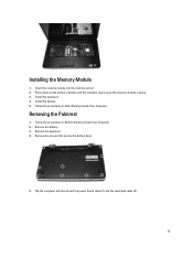
Insert the memory module into the memory socket. 2. Remove the screws that secure the bottom base. 5. Removing the Palmrest 1. Remove the battery. 3. Remove the keyboard. 4. Installing the Memory Module 1. Install the battery. 5. Follow the procedures in Before Working Inside Your Computer. 2. Flip the computer and disconnect the power board cable (1) and the touchpad cable (2). 15 Follow the procedures in After Working Inside Your Computer. Press down on the memory module until the retention clips secure the memory module in place. 3. Install the keyboard. 4.
Insert the memory module into the memory socket. 2. Remove the screws that secure the bottom base. 5. Removing the Palmrest 1. Remove the battery. 3. Remove the keyboard. 4. Installing the Memory Module 1. Install the battery. 5. Follow the procedures in Before Working Inside Your Computer. 2. Flip the computer and disconnect the power board cable (1) and the touchpad cable (2). 15 Follow the procedures in After Working Inside Your Computer. Press down on the memory module until the retention clips secure the memory module in place. 3. Install the keyboard. 4.
Owner's Manual
Page 17
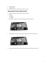
Remove: a) battery b) keyboard c) palmrest 3. Peel the power-button board cable from the adhesive affixing it to the palmrest. 5. Follow the procedures in After Working Inside Your Computer. Install the battery. 8. Follow the procedures in Before Working Inside Your Computer. 2. Lift up the power-button board and release the power-button board cable through the opening. 17 Removing the Power-Button Board 1. Flip the palmrest and remove the screw that secures the power-button board to the palmrest. 4. Install the keyboard. 7. 6.
Remove: a) battery b) keyboard c) palmrest 3. Peel the power-button board cable from the adhesive affixing it to the palmrest. 5. Follow the procedures in After Working Inside Your Computer. Install the battery. 8. Follow the procedures in Before Working Inside Your Computer. 2. Lift up the power-button board and release the power-button board cable through the opening. 17 Removing the Power-Button Board 1. Flip the palmrest and remove the screw that secures the power-button board to the palmrest. 4. Install the keyboard. 7. 6.
Owner's Manual
Page 18
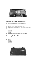
... 6. Fix the power-button board to the palmrest. 5. Removing the Hard Drive 1. Remove: a) battery b) keyboard c) palmrest 3. Installing the Power-Button Board 1. Flip the computer and attach the power-button board cable to its compartment. 3. Follow the procedures in After Working ...
... 6. Fix the power-button board to the palmrest. 5. Removing the Hard Drive 1. Remove: a) battery b) keyboard c) palmrest 3. Installing the Power-Button Board 1. Flip the computer and attach the power-button board cable to its compartment. 3. Follow the procedures in After Working ...

Owner's Manual
Page 19
Place the hard drive in Before Working Inside Your Computer. 2. Install: a) palmrest b) keyboard c) battery 5. Remove: a) battery b) keyboard c) palmrest 3. Removing the Wireless Local Area Network (WLAN) Card 1. Tighten the screws that secure the hard-drive bracket. 3. Disconnect the antennae connected to the hard ...
Place the hard drive in Before Working Inside Your Computer. 2. Install: a) palmrest b) keyboard c) battery 5. Remove: a) battery b) keyboard c) palmrest 3. Removing the Wireless Local Area Network (WLAN) Card 1. Tighten the screws that secure the hard-drive bracket. 3. Disconnect the antennae connected to the hard ...
Owner's Manual
Page 20
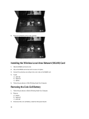
... Follow the procedures in place. 3. Clip on the WLAN card to the latch to the color code on the WLAN card. 4. Remove: a) battery b) keyboard c) palmrest 3. Disconnect the coin-cell battery cable from the computer. Slide the WLAN card into its slot. 2. Install: a) palmrest... b) keyboard c) battery 5. Connect the antennae according to secure it in Before Working Inside Your Computer. 2. 5. Removing the Coin-Cell Battery 1. Installing the Wireless Local ...
... Follow the procedures in place. 3. Clip on the WLAN card to the latch to the color code on the WLAN card. 4. Remove: a) battery b) keyboard c) palmrest 3. Disconnect the coin-cell battery cable from the computer. Slide the WLAN card into its slot. 2. Install: a) palmrest... b) keyboard c) battery 5. Connect the antennae according to secure it in Before Working Inside Your Computer. 2. 5. Removing the Coin-Cell Battery 1. Installing the Wireless Local ...
Owner's Manual
Page 21
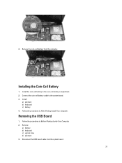
Follow the procedures in the coin-cell battery compartment. 2. Install the coin-cell battery in Before Working Inside Your Computer. 2. Follow the procedures in After Working Inside Your Computer. Remove: a) battery b) keyboard c) optical drive d) palmrest 3. Remove the coin-cell battery from the system board. 21 Installing the Coin-Cell Battery 1. Disconnect the USB board cable from the computer. Removing the USB Board 1. Connect the coin-cell battery cable to the system board. 3. Install: a) palmrest b) keyboard c) battery 4. 4.
Follow the procedures in the coin-cell battery compartment. 2. Install the coin-cell battery in Before Working Inside Your Computer. 2. Follow the procedures in After Working Inside Your Computer. Remove: a) battery b) keyboard c) optical drive d) palmrest 3. Remove the coin-cell battery from the system board. 21 Installing the Coin-Cell Battery 1. Disconnect the USB board cable from the computer. Removing the USB Board 1. Connect the coin-cell battery cable to the system board. 3. Install: a) palmrest b) keyboard c) battery 4. 4.
Owner's Manual
Page 23
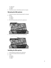
Lift up and remove the microphone from the system board. 4. Insert and align the microphone into its compartment. Installing the Microphone 1. Follow the procedures in After Working Inside Your Computer. Disconnect the microphone cable from its compartment. 2. Connect the microphone cable to the system board. 3. Removing the Microphone 1. b) optical drive c) keyboard d) battery 5. Remove: a) battery b) keyboard c) palmrest 3. Install: a) palmrest b) keyboard c) battery 23 Follow the procedures in Before Working Inside Your Computer. 2.
Lift up and remove the microphone from the system board. 4. Insert and align the microphone into its compartment. Installing the Microphone 1. Follow the procedures in After Working Inside Your Computer. Disconnect the microphone cable from its compartment. 2. Connect the microphone cable to the system board. 3. Removing the Microphone 1. b) optical drive c) keyboard d) battery 5. Remove: a) battery b) keyboard c) palmrest 3. Install: a) palmrest b) keyboard c) battery 23 Follow the procedures in Before Working Inside Your Computer. 2.
Owner's Manual
Page 24
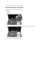
Removing the Heat-Sink Fan Assembly 1. Remove: a) battery b) keyboard c) palmrest 3. Remove the heat-sink fan assembly from the system board. 4. Remove the captive screws that secure the heat-sink fan assembly by following the sequence in Before Working Inside Your Computer. 2. Follow the procedures in the image. 5. Disconnect the CPU-fan cable from the computer. 24 Follow the procedures in After Working Inside Your Computer. 4.
Removing the Heat-Sink Fan Assembly 1. Remove: a) battery b) keyboard c) palmrest 3. Remove the heat-sink fan assembly from the system board. 4. Remove the captive screws that secure the heat-sink fan assembly by following the sequence in Before Working Inside Your Computer. 2. Follow the procedures in the image. 5. Disconnect the CPU-fan cable from the computer. 24 Follow the procedures in After Working Inside Your Computer. 4.
Owner's Manual
Page 25
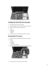
Tighten the captive screws to the system board. 4. Remove: a) battery b) keyboard c) palmrest d) heat-sink fan assembly 3. Removing the Processor 1. Lift up the processor and remove it from the computer. 25 Follow the procedures in Before Working .... 3. Follow the procedures in After Working Inside Your Computer. Installing the Heat-Sink Fan Assembly 1. Place and align the heat-sink fan assembly. 2. Install: a) palmrest b) keyboard c) battery 5. Rotate the processor-cam screw in a counter-clockwise direction. 4.
Tighten the captive screws to the system board. 4. Remove: a) battery b) keyboard c) palmrest d) heat-sink fan assembly 3. Removing the Processor 1. Lift up the processor and remove it from the computer. 25 Follow the procedures in Before Working .... 3. Follow the procedures in After Working Inside Your Computer. Installing the Heat-Sink Fan Assembly 1. Place and align the heat-sink fan assembly. 2. Install: a) palmrest b) keyboard c) battery 5. Rotate the processor-cam screw in a counter-clockwise direction. 4.
Owner's Manual
Page 26
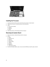
Insert the processor into the processor socket. Install: a) heat-sink fan assembly b) palmrest c) keyboard d) battery 4. Remove: a) battery b) SD memory card c) keyboard d) optical drive e) memory module f) palmrest g) hard drive h) WLAN card i) heat-sink fan assembly 3. Installing the Processor 1. Removing the System Board 1. Ensure the processor is properly ...
Insert the processor into the processor socket. Install: a) heat-sink fan assembly b) palmrest c) keyboard d) battery 4. Remove: a) battery b) SD memory card c) keyboard d) optical drive e) memory module f) palmrest g) hard drive h) WLAN card i) heat-sink fan assembly 3. Installing the Processor 1. Removing the System Board 1. Ensure the processor is properly ...
Owner's Manual
Page 28
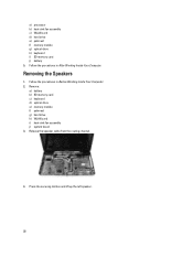
Remove: a) battery b) SD memory card c) keyboard d) optical drive e) memory module f) palmrest g) hard drive h) WLAN card i) heat-sink fan assembly j) system board 3. Follow the procedures in Before Working Inside Your Computer. 2. Press ... the Speakers 1. Follow the procedures in After Working Inside Your Computer. a) processor b) heat-sink fan assembly c) WLAN card d) hard drive e) palmrest f) memory module g) optical drive h) keyboard i) SD memory card j) battery 5.
Remove: a) battery b) SD memory card c) keyboard d) optical drive e) memory module f) palmrest g) hard drive h) WLAN card i) heat-sink fan assembly j) system board 3. Follow the procedures in Before Working Inside Your Computer. 2. Press ... the Speakers 1. Follow the procedures in After Working Inside Your Computer. a) processor b) heat-sink fan assembly c) WLAN card d) hard drive e) palmrest f) memory module g) optical drive h) keyboard i) SD memory card j) battery 5.
Owner's Manual
Page 30
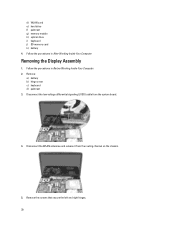
Disconnect the WLAN antennae and release it from the system board. 4. Follow the procedures in After Working Inside Your Computer. Remove the screws that secure the left and right hinges. 30 d) WLAN card e) hard drive f) palmrest g) memory module h) optical drive i) keyboard j) SD memory card k) battery 4. Follow the procedures in Before Working Inside Your Computer. 2. Removing the Display Assembly 1. Disconnect the low-voltage differential signaling (LVDS) cable from the routing channel on the chassis. 5. Remove: a) battery b) hinge cover c) keyboard d) palmrest 3.
Disconnect the WLAN antennae and release it from the system board. 4. Follow the procedures in After Working Inside Your Computer. Remove the screws that secure the left and right hinges. 30 d) WLAN card e) hard drive f) palmrest g) memory module h) optical drive i) keyboard j) SD memory card k) battery 4. Follow the procedures in Before Working Inside Your Computer. 2. Removing the Display Assembly 1. Disconnect the low-voltage differential signaling (LVDS) cable from the routing channel on the chassis. 5. Remove: a) battery b) hinge cover c) keyboard d) palmrest 3.


