Setup and Quick Reference Guide
Page 38
...the problem persists, contact Dell (see "Contacting Dell" on the system board may be loose. The time or date stored in the Dell Diagnostics (see your computer. A chip on page 64). The keyboard controller may be malfunctioning,...E T U P P R O G R A M - Run the System Set tests in Lockups and Software Problems (see "Dell Diagnostics" on page 38). Run the System Memory tests and the Keyboard Controller test in the system setup program does not match the system clock. D A Y N O T S E T - Replace the battery, or connect the computer to charge the battery. The reserve battery...
...the problem persists, contact Dell (see "Contacting Dell" on the system board may be loose. The time or date stored in the Dell Diagnostics (see your computer. A chip on page 64). The keyboard controller may be malfunctioning,...E T U P P R O G R A M - Run the System Set tests in Lockups and Software Problems (see "Dell Diagnostics" on page 38). Run the System Memory tests and the Keyboard Controller test in the system setup program does not match the system clock. D A Y N O T S E T - Replace the battery, or connect the computer to charge the battery. The reserve battery...
Service Manual
Page 2
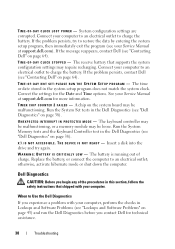
...Memory Module), then reinstall one at www.dell.com/regulatory_compliance. If the computer starts normally, continue to install additional memory modules (one module (see Memory). For additional safety best practices information, see Replacing a Memory Module) and restart the computer... Vostro™ 2510 Service Manual Troubleshooting Tools Solving Problems Dell Technical Update Service Dell Support Utility Troubleshooting Tools Diagnostic Lights CAUTION: Before working inside your computer, read the safety information that shipped with your computer, read the sequence of the keyboard...
...Memory Module), then reinstall one at www.dell.com/regulatory_compliance. If the computer starts normally, continue to install additional memory modules (one module (see Memory). For additional safety best practices information, see Replacing a Memory Module) and restart the computer... Vostro™ 2510 Service Manual Troubleshooting Tools Solving Problems Dell Technical Update Service Dell Support Utility Troubleshooting Tools Diagnostic Lights CAUTION: Before working inside your computer, read the safety information that shipped with your computer, read the sequence of the keyboard...
Service Manual
Page 12
.... Eliminate interference - For additional safety best practices information, see Replacing a Memory Module). Always check to verify that shipped with the memory. See the software documentation for your computer. Run the Dell Diagnostics (see Dell Diagnostics). Ensure that your computer is not muted. If you... (see the Regulatory Compliance Homepage at support.dell.com. If you are using to ensure that any open files and exit any power strips being used are plugged into an electrical outlet and are : Power, keyboard, and mouse extension cables Too many devices...
.... Eliminate interference - For additional safety best practices information, see Replacing a Memory Module). Always check to verify that shipped with the memory. See the software documentation for your computer. Run the Dell Diagnostics (see Dell Diagnostics). Ensure that your computer is not muted. If you... (see the Regulatory Compliance Homepage at support.dell.com. If you are using to ensure that any open files and exit any power strips being used are plugged into an electrical outlet and are : Power, keyboard, and mouse extension cables Too many devices...
Service Manual
Page 36
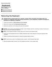
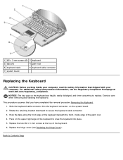
... to ensure that you do not pull on the system board. Rotate the retaining bracket upward to Contents Page Keyboard Dell™ Vostro™ 2510 Service Manual Removing the Keyboard Replacing the Keyboard Removing the Keyboard CAUTION: Before working inside your computer, read the safety information that shipped with your computer. Exercise care when removing and handling the...
... to ensure that you do not pull on the system board. Rotate the retaining bracket upward to Contents Page Keyboard Dell™ Vostro™ 2510 Service Manual Removing the Keyboard Replacing the Keyboard Removing the Keyboard CAUTION: Before working inside your computer, read the safety information that shipped with your computer. Exercise care when removing and handling the...
Service Manual
Page 37
... along the front edge of the keyboard. 6. Replace the hinge cover (see the Regulatory Compliance Homepage at the top of the keyboard beneath the front- Back to secure the keyboard cable connector. 3. on the keyboard are fragile, easily dislodged, and time-consuming to replace. Replace the two M2 x 3-mm screws at www.dell.com/regulatory_compliance. NOTICE: The key...
... along the front edge of the keyboard. 6. Replace the hinge cover (see the Regulatory Compliance Homepage at the top of the keyboard beneath the front- Back to secure the keyboard cable connector. 3. on the keyboard are fragile, easily dislodged, and time-consuming to replace. Replace the two M2 x 3-mm screws at www.dell.com/regulatory_compliance. NOTICE: The key...
Service Manual
Page 40
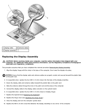
... lower the display into the base of the display assembly. 3. In sequential order, replace the four M2.5 x 5-mm screws on the palm rest. 4. Replace the hinge cover (see the Regulatory Compliance Homepage at www.dell.com/regulatory_compliance. Replace the M2.5 x 8-mm screw that attaches the display assembly to the display cable connector... you have completed the removal procedure Removing the Display Assembly. 1. Close the display and turn the computer upside down. 10. In sequential order, replace the four M2.5 x 5-mm screws into place. Replace the keyboard (see Replacing the Keyboard). 8.
... lower the display into the base of the display assembly. 3. In sequential order, replace the four M2.5 x 5-mm screws on the palm rest. 4. Replace the hinge cover (see the Regulatory Compliance Homepage at www.dell.com/regulatory_compliance. Replace the M2.5 x 8-mm screw that attaches the display assembly to the display cable connector... you have completed the removal procedure Removing the Display Assembly. 1. Close the display and turn the computer upside down. 10. In sequential order, replace the four M2.5 x 5-mm screws into place. Replace the keyboard (see Replacing the Keyboard). 8.
Service Manual
Page 41
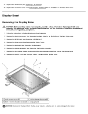
... Computer. 2. See Removing the Hard Drive for an illustration of the hard drive cover. Remove the keyboard (see the Regulatory Compliance Homepage at www.dell.com/regulatory_compliance. 1. See Removing the Hard Drive for an illustration of the bezel from around the display...drive cover. 3. For additional safety best practices information, see Removing the Keyboard). 6. Remove the hinge cover (see Removing the Display Assembly). 7. Remove the display assembly (see Removing the Hinge Cover). 5. Replace the hard drive cover. Remove the six M2.5 x 5-mm shoulder screws...
... Computer. 2. See Removing the Hard Drive for an illustration of the hard drive cover. Remove the keyboard (see the Regulatory Compliance Homepage at www.dell.com/regulatory_compliance. 1. See Removing the Hard Drive for an illustration of the bezel from around the display...drive cover. 3. For additional safety best practices information, see Removing the Keyboard). 6. Remove the hinge cover (see Removing the Display Assembly). 7. Remove the display assembly (see Removing the Hinge Cover). 5. Replace the hard drive cover. Remove the six M2.5 x 5-mm shoulder screws...
Service Manual
Page 42
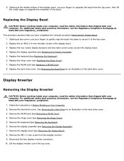
... panel, use your computer. 9. Remove the display assembly (see Removing the Keyboard). 6. For additional safety best practices information, see the Regulatory Compliance Homepage at www.dell.com/regulatory_compliance. Remove the keyboard (see Removing the Display Assembly). 7. Remove the display bezel (see Replacing the Hinge Cover). 7. Lift the display inverter out of the hard drive...
... panel, use your computer. 9. Remove the display assembly (see Removing the Keyboard). 6. For additional safety best practices information, see the Regulatory Compliance Homepage at www.dell.com/regulatory_compliance. Remove the keyboard (see Removing the Display Assembly). 7. Remove the display bezel (see Replacing the Hinge Cover). 7. Lift the display inverter out of the hard drive...
Service Manual
Page 43
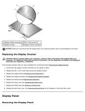
...completed the removal procedure Removing the Display Inverter. 1. Replace the display bezel (seeReplacing the Display Bezel). 4. Replace the display assembly (see the Regulatory Compliance Homepage at www.dell.com/regulatory_compliance. This procedure assumes that secures the ... display inverter 4 display inverter connector NOTICE: Removal of the hard drive cover. Replacing the Display Inverter CAUTION: Before working inside your computer, read the safety information that shipped with your computer. Replace the hard drive cover. Replace the keyboard (see Replacing the Keyboard). 6.
...completed the removal procedure Removing the Display Inverter. 1. Replace the display bezel (seeReplacing the Display Bezel). 4. Replace the display assembly (see the Regulatory Compliance Homepage at www.dell.com/regulatory_compliance. This procedure assumes that secures the ... display inverter 4 display inverter connector NOTICE: Removal of the hard drive cover. Replacing the Display Inverter CAUTION: Before working inside your computer, read the safety information that shipped with your computer. Replace the hard drive cover. Replace the keyboard (see Replacing the Keyboard). 6.
Service Manual
Page 44
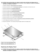
... Remove the hinge cover (see Removing the Keyboard). 6. Remove the eight M2 x 3-mm screws securing the display bracket to the display panel. 1 M2 x 5-mm screws (2) 2 display panel 3 M2 x 3-mm screws (8) 4 top cover Replacing the Display Panel CAUTION: Before working inside...For additional safety best practices information, see the Regulatory Compliance Homepage at www.dell.com/regulatory_compliance. For additional safety best practices information, see the Regulatory Compliance Homepage at www.dell.com/regulatory_compliance. 1. Remove the WLAN card (see Removing the Display Bezel...
... Remove the hinge cover (see Removing the Keyboard). 6. Remove the eight M2 x 3-mm screws securing the display bracket to the display panel. 1 M2 x 5-mm screws (2) 2 display panel 3 M2 x 3-mm screws (8) 4 top cover Replacing the Display Panel CAUTION: Before working inside...For additional safety best practices information, see the Regulatory Compliance Homepage at www.dell.com/regulatory_compliance. For additional safety best practices information, see the Regulatory Compliance Homepage at www.dell.com/regulatory_compliance. 1. Remove the WLAN card (see Removing the Display Bezel...
Service Manual
Page 45
... the display bracket. 11. Replace the keyboard (see Replacing a WLAN Card). 12. Replace the WLAN card (see Replacing the Keyboard). 10. Remove the WLAN card (see Replacing the Display Bezel). 8. This... procedure assumes that shipped with your computer, read the safety information that you have completed the removal procedure Removing the Display Panel. 1. Replace the eight M2 x 3-mm screws in the top cover. 3. Align the guide pins at www.dell.com/regulatory_compliance. 1. Replace...
... the display bracket. 11. Replace the keyboard (see Replacing a WLAN Card). 12. Replace the WLAN card (see Replacing the Keyboard). 10. Remove the WLAN card (see Replacing the Display Bezel). 8. This... procedure assumes that shipped with your computer, read the safety information that you have completed the removal procedure Removing the Display Panel. 1. Replace the eight M2 x 3-mm screws in the top cover. 3. Align the guide pins at www.dell.com/regulatory_compliance. 1. Replace...
Service Manual
Page 46
... the Hard Drive for an illustration of the display panel. 2. Align the guide pins at www.dell.com/regulatory_compliance. Replace the keyboard (see Replacing the Display Inverter). 5. Replace the hinge cover (see Replacing a WLAN Card). 10. Replace the WLAN card (see Replacing the Hinge Cover). 9. Camera and Microphone Assembly Removing the Camera and Microphone Assembly CAUTION: Before working...
... the Hard Drive for an illustration of the display panel. 2. Align the guide pins at www.dell.com/regulatory_compliance. Replace the keyboard (see Replacing the Display Inverter). 5. Replace the hinge cover (see Replacing a WLAN Card). 10. Replace the WLAN card (see Replacing the Hinge Cover). 9. Camera and Microphone Assembly Removing the Camera and Microphone Assembly CAUTION: Before working...
Service Manual
Page 47
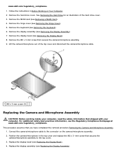
...the camera/microphone in Before Working on the camera/microphone assembly. 2. www.dell.com/regulatory_compliance. 1. Remove the hard drive cover. Replace the display assembly (see Replacing the Display Bezel). 4. Lift the camera/microphone out of the hard ...drive cover. 3. Connect the camera/microphone cable to the top cover. 3. mm screw that you have completed the removal procedure Removing the Camera and Microphone Assembly. 1. Remove the hinge cover (see Removing the Keyboard). 6. Remove the keyboard...
...the camera/microphone in Before Working on the camera/microphone assembly. 2. www.dell.com/regulatory_compliance. 1. Remove the hard drive cover. Replace the display assembly (see Replacing the Display Bezel). 4. Lift the camera/microphone out of the hard ...drive cover. 3. Connect the camera/microphone cable to the top cover. 3. mm screw that you have completed the removal procedure Removing the Camera and Microphone Assembly. 1. Remove the hinge cover (see Removing the Keyboard). 6. Remove the keyboard...

Service Manual
Page 48
5. See Removing the Hard Drive for an illustration of the hard drive cover. Replace the hinge cover (see Replacing the Keyboard). 6. Replace the hard drive cover. Back to Contents Page Replace the keyboard (see Replacing the Hinge Cover). 7. Replace the WLAN card (see Replacing a WLAN Card). 8.
5. See Removing the Hard Drive for an illustration of the hard drive cover. Replace the hinge cover (see Replacing the Keyboard). 6. Replace the hard drive cover. Back to Contents Page Replace the keyboard (see Replacing the Hinge Cover). 7. Replace the WLAN card (see Replacing a WLAN Card). 8.
Service Manual
Page 49
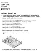
... display assembly (see Removing a WLAN Card). 5. Remove the hinge cover (see Removing the Keyboard). 7. Back to Contents Page Palm Rest Dell™ Vostro™ 2510 Service Manual Removing the Palm Rest Replacing the Palm Rest Removing the Palm Rest CAUTION: Before working inside your computer. Remove any cards...Hard Drive for an illustration of the palm rest. Remove the fourteen M2.5 x 8-mm screws from the image shown below. 10. Remove the keyboard (see Removing the Hinge Cover). 6. Follow the instructions in - 1 card slot. 4. Turn the computer over and remove the three M2.5 ...
... display assembly (see Removing a WLAN Card). 5. Remove the hinge cover (see Removing the Keyboard). 7. Back to Contents Page Palm Rest Dell™ Vostro™ 2510 Service Manual Removing the Palm Rest Replacing the Palm Rest Removing the Palm Rest CAUTION: Before working inside your computer. Remove any cards...Hard Drive for an illustration of the palm rest. Remove the fourteen M2.5 x 8-mm screws from the image shown below. 10. Remove the keyboard (see Removing the Hinge Cover). 6. Follow the instructions in - 1 card slot. 4. Turn the computer over and remove the three M2.5 ...
Service Manual
Page 51
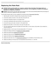
... upside down and replace the fourteen M2.5 x 8-mm screws on the bottom of the hard drive cover. 14. Replace the keyboard (see Replacing the Hinge Cover)....Replace the three M2.5 x 5-mm screws on the fan. 9. Replace the hinge cover (see Replacing the Keyboard). 11. Connect the touchpad connector to Contents Page Replace the M2.5 x 5-mm screw in -1 card slot. Replace the WLAN card (see Replacing...connector to the system board. 6. Replace the display assembly (see Replacing a WLAN Card). 13. Replace the hard drive cover. Replace any blanks you have completed the removal...
... upside down and replace the fourteen M2.5 x 8-mm screws on the bottom of the hard drive cover. 14. Replace the keyboard (see Replacing the Hinge Cover)....Replace the three M2.5 x 5-mm screws on the fan. 9. Replace the hinge cover (see Replacing the Keyboard). 11. Connect the touchpad connector to Contents Page Replace the M2.5 x 5-mm screw in -1 card slot. Replace the WLAN card (see Replacing...connector to the system board. 6. Replace the display assembly (see Replacing a WLAN Card). 13. Replace the hard drive cover. Replace any blanks you have completed the removal...
Service Manual
Page 52
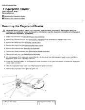
... Follow the instructions in Before Working on the palm rest upward to Contents Page Fingerprint Reader Dell™ Vostro™ 2510 Service Manual Removing the Fingerprint Reader Replacing the Fingerprint Reader Removing the Fingerprint Reader CAUTION: Before working inside your computer, read the ... display assembly (see Removing a WLAN Card). 4. reader cable connector. 10. Remove the hinge cover (see Removing the Keyboard). 6. Remove the keyboard (see Removing the Hinge Cover). 5. Remove the fingerprint reader from the fingerprint reader cover, and lift the fingerprint reader ...
... Follow the instructions in Before Working on the palm rest upward to Contents Page Fingerprint Reader Dell™ Vostro™ 2510 Service Manual Removing the Fingerprint Reader Replacing the Fingerprint Reader Removing the Fingerprint Reader CAUTION: Before working inside your computer, read the ... display assembly (see Removing a WLAN Card). 4. reader cable connector. 10. Remove the hinge cover (see Removing the Keyboard). 6. Remove the keyboard (see Removing the Hinge Cover). 5. Remove the fingerprint reader from the fingerprint reader cover, and lift the fingerprint reader ...
Service Manual
Page 53
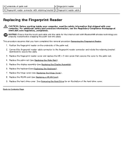
... Display Assembly). 6. Position the fingerprint reader on the underside of the hard drive cover. Replace the display assembly (see Replacing a WLAN Card). 9. Replace the hard drive cover. Replace the keyboard (see the Regulatory Compliance Homepage at www.dell.com/regulatory_compliance. Back to secure the cable. 3. This procedure assumes that secures the cover to the palm rest...
... Display Assembly). 6. Position the fingerprint reader on the underside of the hard drive cover. Replace the display assembly (see Replacing a WLAN Card). 9. Replace the hard drive cover. Replace the keyboard (see the Regulatory Compliance Homepage at www.dell.com/regulatory_compliance. Back to secure the cable. 3. This procedure assumes that secures the cover to the palm rest...
Service Manual
Page 54
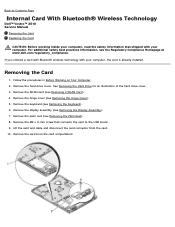
...the Regulatory Compliance Homepage at www.dell.com/regulatory_compliance. Remove the M2 x 3-mm screw that shipped with your computer, the card is already installed. Remove the keyboard (see Removing a WLAN Card). 4. Remove the WLAN card (see Removing the Keyboard). 6. Lift the card and ...Remove the card from the card. 10. Back to Contents Page Internal Card With Bluetooth® Wireless Technology Dell™ Vostro™ 2510 Service Manual Removing the Card Replacing the Card CAUTION: Before working inside your computer, read the safety information that connects the card to the ...
...the Regulatory Compliance Homepage at www.dell.com/regulatory_compliance. Remove the M2 x 3-mm screw that shipped with your computer, the card is already installed. Remove the keyboard (see Removing a WLAN Card). 4. Remove the WLAN card (see Removing the Keyboard). 6. Lift the card and ...Remove the card from the card. 10. Back to Contents Page Internal Card With Bluetooth® Wireless Technology Dell™ Vostro™ 2510 Service Manual Removing the Card Replacing the Card CAUTION: Before working inside your computer, read the safety information that connects the card to the ...
Service Manual
Page 55
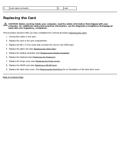
... safety information that shipped with your computer. Replace the hinge cover (see Replacing a WLAN Card). 9. See Removing the Hard Drive for an illustration of the hard drive cover. For additional safety best practices information, see Replacing the Keyboard). 7. Replace the keyboard (see the Regulatory Compliance Homepage at www.dell.com/regulatory_compliance. Replace the card in the card compartment...
... safety information that shipped with your computer. Replace the hinge cover (see Replacing a WLAN Card). 9. See Removing the Hard Drive for an illustration of the hard drive cover. For additional safety best practices information, see Replacing the Keyboard). 7. Replace the keyboard (see the Regulatory Compliance Homepage at www.dell.com/regulatory_compliance. Replace the card in the card compartment...


