Setup and Features Information Tech Sheet
Page 2
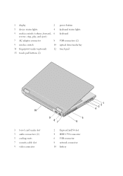
1 display 2 3 device status lights 4 5 media controls (volume, forward, 6 reverse, stop, play, and eject) 7 AC adapter connector 8 9 wireless switch 10 11 fingerprint reader (optional) 12 13 touch pad buttons (2) power button keyboard status lights keyboard USB connectors (2) optical drive/media bay touch pad 10 1 8-in-1 card reader slot 3 audio connectors (2) 5 cooling vents 7 security cable slot 9 video connector 9 87 5 6 2 ExpressCard/54 slot 4 IEEE 1394 connector 6 USB connector 8 network connector 10 battery 3 21 4
1 display 2 3 device status lights 4 5 media controls (volume, forward, 6 reverse, stop, play, and eject) 7 AC adapter connector 8 9 wireless switch 10 11 fingerprint reader (optional) 12 13 touch pad buttons (2) power button keyboard status lights keyboard USB connectors (2) optical drive/media bay touch pad 10 1 8-in-1 card reader slot 3 audio connectors (2) 5 cooling vents 7 security cable slot 9 video connector 9 87 5 6 2 ExpressCard/54 slot 4 IEEE 1394 connector 6 USB connector 8 network connector 10 battery 3 21 4
Setup and Features Information Tech Sheet
Page 4
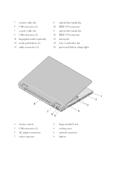
7 security cable slot 9 USB connectors (2) 7 security cable slot 9 USB connectors (2) 11 fingerprint reader (optional) 13 touch pad buttons (2) 15 audio connectors (2) 8 optical drive/media bay 10 IEEE 1394 connector 8 optical drive/media bay 10 IEEE 1394 connector 12 touch pad 14 8-in-1 card reader slot 16 power and battery charge lights 8 7 4 65 1 wireless switch 3 USB connectors (2) 5 AC adapter connector 7 video connector 2 ExpressCard/54 slot 4 cooling vents 6 network connector 8 battery 1 2 3
7 security cable slot 9 USB connectors (2) 7 security cable slot 9 USB connectors (2) 11 fingerprint reader (optional) 13 touch pad buttons (2) 15 audio connectors (2) 8 optical drive/media bay 10 IEEE 1394 connector 8 optical drive/media bay 10 IEEE 1394 connector 12 touch pad 14 8-in-1 card reader slot 16 power and battery charge lights 8 7 4 65 1 wireless switch 3 USB connectors (2) 5 AC adapter connector 7 video connector 2 ExpressCard/54 slot 4 cooling vents 6 network connector 8 battery 1 2 3

Setup and Features Information Tech Sheet
Page 6
...6 1 2 3 1 USB connector 3 USB connectors (2) 5 USB connector 7 network connector 9 battery 2 ExpressCard/54 slot 4 cooling vents 6 AC adapter connector 8 video connector WARNING: Do not block, push objects into, or allow dust to the power strip or electrical outlet may cause fire or equipment...environment, such as a closed briefcase, while it is normal and does not indicate a problem with your Dell™ computer in the air vents. Fan noise is running. WARNING: The AC adapter works with electrical outlets worldwide. The computer turns on the fan when the computer gets hot. Do not...
...6 1 2 3 1 USB connector 3 USB connectors (2) 5 USB connector 7 network connector 9 battery 2 ExpressCard/54 slot 4 cooling vents 6 AC adapter connector 8 video connector WARNING: Do not block, push objects into, or allow dust to the power strip or electrical outlet may cause fire or equipment...environment, such as a closed briefcase, while it is normal and does not indicate a problem with your Dell™ computer in the air vents. Fan noise is running. WARNING: The AC adapter works with electrical outlets worldwide. The computer turns on the fan when the computer gets hot. Do not...

Setup and Features Information Tech Sheet
Page 7
..., ensure that you follow the angle of the connector on the computer. CAUTION: When you did not order them. 1 Connect the AC adapter to the AC adapter connector on the computer and to the electrical outlet. 2 Connect the network cable. 3 Connect USB devices, such as a mouse or keyboard. 4 Connect...a DVD player. 5 Open the computer display and press the power button to turn on the AC adapter to avoid damaging the cable. NOTE: Some devices may not be included if you disconnect the AC adapter cable from the computer, grasp the connector, not the cable itself, and pull firmly but gently...
..., ensure that you follow the angle of the connector on the computer. CAUTION: When you did not order them. 1 Connect the AC adapter to the AC adapter connector on the computer and to the electrical outlet. 2 Connect the network cable. 3 Connect USB devices, such as a mouse or keyboard. 4 Connect...a DVD player. 5 Open the computer display and press the power button to turn on the AC adapter to avoid damaging the cable. NOTE: Some devices may not be included if you disconnect the AC adapter cable from the computer, grasp the connector, not the cable itself, and pull firmly but gently...
Setup and Features Information Tech Sheet
Page 9
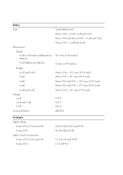
... (2.835 inches) Vostro 1310 - 19.9 mm (0.783 inch) Vostro 1310 - 20.7 mm (0.815 inch) Vostro 1510 and 2510 - 19.9 mm (0.783 inch) Vostro 1510 and 2510 - 20.7 mm (0.815 inch) Vostro 1710 - 20.2 mm (0.795 inch) 14.8 V 11.1 V 16.8 V CR-2032 AC Adapter Input voltage Vostro 1310, 1510, and 1710 Vostro 2510 Input current (maximum) Vostro 1310, 1510, and 1710 Vostro 2510 90-264 VAC...
... (2.835 inches) Vostro 1310 - 19.9 mm (0.783 inch) Vostro 1310 - 20.7 mm (0.815 inch) Vostro 1510 and 2510 - 19.9 mm (0.783 inch) Vostro 1510 and 2510 - 20.7 mm (0.815 inch) Vostro 1710 - 20.2 mm (0.795 inch) 14.8 V 11.1 V 16.8 V CR-2032 AC Adapter Input voltage Vostro 1310, 1510, and 1710 Vostro 2510 Input current (maximum) Vostro 1310, 1510, and 1710 Vostro 2510 90-264 VAC...

Setup and Features Information Tech Sheet
Page 10
...pulse) 3.34 A (continuous) 90 W 5.62 A (maximum at 4-second pulse) 4.62 A (continuous) NOTE: On Vostro 1510/1710/2510 computers that have a discrete video configuration, you must use the 90W AC adapter that is shipped with cables) 0.46 kg (1.01 lbs) Temperature range 0° to 35° C (32° ...to 95° F) Using an incorrect AC adapter will prevent optimal system performance and produce a BIOS warning. Rated output voltage Vostro 1310, 1510, and 1710 19.5 VDC (65 W and 90 W) Vostro 2510 19.5 VDC (90 W) Dimensions (65 W): Height 27.8-28.6 mm (1.10...
...pulse) 3.34 A (continuous) 90 W 5.62 A (maximum at 4-second pulse) 4.62 A (continuous) NOTE: On Vostro 1510/1710/2510 computers that have a discrete video configuration, you must use the 90W AC adapter that is shipped with cables) 0.46 kg (1.01 lbs) Temperature range 0° to 35° C (32° ...to 95° F) Using an incorrect AC adapter will prevent optimal system performance and produce a BIOS warning. Rated output voltage Vostro 1310, 1510, and 1710 19.5 VDC (65 W and 90 W) Vostro 2510 19.5 VDC (90 W) Dimensions (65 W): Height 27.8-28.6 mm (1.10...
Setup and Quick Reference Guide
Page 9
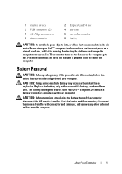
... with a compatible battery purchased from other external cables from the computer. The battery is normal and does not indicate a problem with your Dell™ computer. 1 wireless switch 3 USB connectors (2) 5 AC Adapter connector 7 video connector 2 ExpressCard/54 slot 4 air vents 6 network connector 8 battery CAUTION: Do not block, push objects into, or allow dust to...
... with a compatible battery purchased from other external cables from the computer. The battery is normal and does not indicate a problem with your Dell™ computer. 1 wireless switch 3 USB connectors (2) 5 AC Adapter connector 7 video connector 2 ExpressCard/54 slot 4 air vents 6 network connector 8 battery CAUTION: Do not block, push objects into, or allow dust to...
Setup and Quick Reference Guide
Page 11
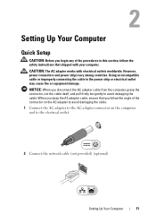
..., and pull firmly but gently to the power strip or electrical outlet may cause fire or equipment damage. When you wrap the AC adapter cable, ensure that you follow the angle of the procedures in this section, follow the safety instructions that shipped with electrical outlets ... damaging the cable. Setting Up Your Computer Quick Setup CAUTION: Before you begin any of the connector on the AC adapter to avoid damaging the cable. 1 Connect the AC adapter to the AC adapter connector on the computer and to the electrical outlet. 2 Connect the network cable (not provided) (optional). CAUTION...
..., and pull firmly but gently to the power strip or electrical outlet may cause fire or equipment damage. When you wrap the AC adapter cable, ensure that you follow the angle of the procedures in this section, follow the safety instructions that shipped with electrical outlets ... damaging the cable. Setting Up Your Computer Quick Setup CAUTION: Before you begin any of the connector on the AC adapter to avoid damaging the cable. 1 Connect the AC adapter to the AC adapter connector on the computer and to the electrical outlet. 2 Connect the network cable (not provided) (optional). CAUTION...

Setup and Quick Reference Guide
Page 27
... (65 W and 90 W) Output current (65 W) 4.34 A (maximum at 4-second pulse) 3.34 A (continuous) Output current (90 W) 5.62 A (maximum at 4-second pulse) 4.62 A (continuous) NOTE: On Vostro computers (except Vostro 1310) with discrete video configuration, you must use a 90 W AC adapter that is shipped with your computer.
... (65 W and 90 W) Output current (65 W) 4.34 A (maximum at 4-second pulse) 3.34 A (continuous) Output current (90 W) 5.62 A (maximum at 4-second pulse) 4.62 A (continuous) NOTE: On Vostro computers (except Vostro 1310) with discrete video configuration, you must use a 90 W AC adapter that is shipped with your computer.
Setup and Quick Reference Guide
Page 28
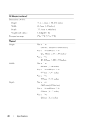
AC Adapter (continued) Dimensions (90 W): Height Width Depth Weight (with cables) Temperature range Physical Height Width Depth 33.8-34.6 mm (1.34-1.36 inches) 60.9 mm (2.39 inches) 153.4 mm (6.04 inches) 0.46 kg (1.01 lb) 0° to 35°C (32° to 95°F) Vostro 1310: • 23.8-37.2 mm (0.937-1.465 inches) Vostro 1510...
AC Adapter (continued) Dimensions (90 W): Height Width Depth Weight (with cables) Temperature range Physical Height Width Depth 33.8-34.6 mm (1.34-1.36 inches) 60.9 mm (2.39 inches) 153.4 mm (6.04 inches) 0.46 kg (1.01 lb) 0° to 35°C (32° to 95°F) Vostro 1310: • 23.8-37.2 mm (0.937-1.465 inches) Vostro 1510...

Service Manual
Page 32
... connector. 1 securing clips (2) 2 memory module Replacing a Memory Module CAUTION: Before working inside your computer. Slide the module firmly into the battery bay, or connect the AC adapter to your computer. 3. This procedure assumes that shipped with the tab in the connector slot. 2. If you have completed the removal procedure Removing a Memory Module... difficult to close , remove the module and reinstall it . Replace the memory cover and tighten the screws. 4. Insert the battery into the slot at www.dell.com/regulatory_compliance.
... connector. 1 securing clips (2) 2 memory module Replacing a Memory Module CAUTION: Before working inside your computer. Slide the module firmly into the battery bay, or connect the AC adapter to your computer. 3. This procedure assumes that shipped with the tab in the connector slot. 2. If you have completed the removal procedure Removing a Memory Module... difficult to close , remove the module and reinstall it . Replace the memory cover and tighten the screws. 4. Insert the battery into the slot at www.dell.com/regulatory_compliance.
Service Manual
Page 71
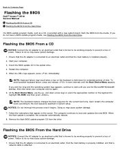
... the Boot Device Menu, use the up- Remove the flash BIOS update program CD from the media. Back to Contents Page Flashing the BIOS Dell™ Vostro™ 2510 Service Manual Flashing the BIOS From a CD Flashing the BIOS From the Hard Drive If a BIOS-update program media, such as a CD,... wait too long and the operating system logo appears, continue to an electrical outlet, that the main battery is properly installed, and that the AC adapter is connected to wait until the Boot Device Menu appears. Insert the BIOS-update CD in the optical drive. 4. Failure to boot and updates...
... the Boot Device Menu, use the up- Remove the flash BIOS update program CD from the media. Back to Contents Page Flashing the BIOS Dell™ Vostro™ 2510 Service Manual Flashing the BIOS From a CD Flashing the BIOS From the Hard Drive If a BIOS-update program media, such as a CD,... wait too long and the operating system logo appears, continue to an electrical outlet, that the main battery is properly installed, and that the AC adapter is connected to wait until the Boot Device Menu appears. Insert the BIOS-update CD in the optical drive. 4. Failure to boot and updates...


