Dell™ Technology Guide
Page 302
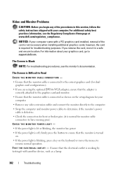
... with your computer. The Screen is Blank NOTE: For troubleshooting procedures, see the Regulatory Compliance Homepage at www.dell.com/regulatory_compliance. TE S T T H E E L E C T R I C A L O U T L E T - however, the card is working by testing it in this section, follow the safety instructions shipped with a PCI graphics card installed, removal of the procedures in a safe and secure location. Ensure that the...
... with your computer. The Screen is Blank NOTE: For troubleshooting procedures, see the Regulatory Compliance Homepage at www.dell.com/regulatory_compliance. TE S T T H E E L E C T R I C A L O U T L E T - however, the card is working by testing it in this section, follow the safety instructions shipped with a PCI graphics card installed, removal of the procedures in a safe and secure location. Ensure that the...
Dell™ Technology Guide
Page 343
...ESD can damage integrated circuits found in some countries. expansion card - Examples include video, modem, and sound cards. A connector on the system board (in an expansion slot on your display. ExpressCards support both the PCI Express and USB 2.0 standard. Express Service Code - ... connector design that extends beyond the edge of your Dell™ computer. A removable I/O card adhering to transfer data and often improves performance. Express Service Code service may not be available in computer and communications equipment. Also see Service Tag. An improved...
...ESD can damage integrated circuits found in some countries. expansion card - Examples include video, modem, and sound cards. A connector on the system board (in an expansion slot on your display. ExpressCards support both the PCI Express and USB 2.0 standard. Express Service Code - ... connector design that extends beyond the edge of your Dell™ computer. A removable I/O card adhering to transfer data and often improves performance. Express Service Code service may not be available in computer and communications equipment. Also see Service Tag. An improved...
Dell™ Technology Guide
Page 347
... is functionally equivalent to as a synonym for digital cameras. megahertz - MP - Your computer can access. MHz - The speeds for integrated peripherals, such as a NIC (network interface controller). A Mini PCI card is a small external card that equals 1 million cycles per second. Mini-Card - module bay - See media bay. Access times of image resolution used as system...
... is functionally equivalent to as a synonym for digital cameras. megahertz - MP - Your computer can access. MHz - The speeds for integrated peripherals, such as a NIC (network interface controller). A Mini PCI card is a small external card that equals 1 million cycles per second. Mini-Card - module bay - See media bay. Access times of image resolution used as system...
Dell™ Technology Guide
Page 348
... rows and columns to the PCMCIA standard. PCI is turned off or loses its external power source. PCI Express - A modification to 4 GB/sec. If the PCI Express chip set . PIO - POST - power-on a display screen. ns - O optical drive - Personal Computer Memory Card International Association - The ability of PC Cards. Plug and Play provides automatic installation, configuration...
... rows and columns to the PCMCIA standard. PCI is turned off or loses its external power source. PCI Express - A modification to 4 GB/sec. If the PCI Express chip set . PIO - POST - power-on a display screen. ns - O optical drive - Personal Computer Memory Card International Association - The ability of PC Cards. Plug and Play provides automatic installation, configuration...
Setup and Quick Reference Guide
Page 32
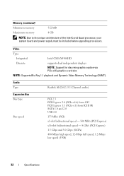
... Type: Integrated Intel GMA X4500HD Discrete supports dual independent displays NOTE: Support for discrete graphics option via PCIe x16 graphics card slot. Memory (continued) Minimum memory 512 MB Maximum memory 4 GB NOTE: Due to the unique architecture of the ...ALC662 (5.1 Channel audio) Expansion Bus Bus type Bus speed PCI 2.3 PCI Express 2.0 (PCIe-x16) from G45 PCI Express 1.1 (PCIe-x1) from ICH10R SATA 1.0 and 2.0 USB 2.0 133 MB/s (PCI) x1-slot bidirectional speed - 500 MB/s (PCI Express) x16-slot bidirectional speed - 8 GB/s (PCI Express) 1.5 Gbps and 3.0 Gbps (SATA) 480-Mbps...
... Type: Integrated Intel GMA X4500HD Discrete supports dual independent displays NOTE: Support for discrete graphics option via PCIe x16 graphics card slot. Memory (continued) Minimum memory 512 MB Maximum memory 4 GB NOTE: Due to the unique architecture of the ...ALC662 (5.1 Channel audio) Expansion Bus Bus type Bus speed PCI 2.3 PCI Express 2.0 (PCIe-x16) from G45 PCI Express 1.1 (PCIe-x1) from ICH10R SATA 1.0 and 2.0 USB 2.0 133 MB/s (PCI) x1-slot bidirectional speed - 500 MB/s (PCI Express) x16-slot bidirectional speed - 8 GB/s (PCI Express) 1.5 Gbps and 3.0 Gbps (SATA) 480-Mbps...
Service Manual
Page 5
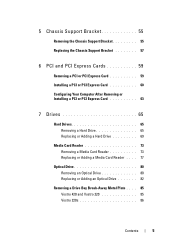
... Support Bracket 55 Replacing the Chassis Support Bracket 57 6 PCI and PCI Express Cards 59 Removing a PCI or PCI Express Card 59 Installing a PCI or PCI Express Card 60 Configuring Your Computer After Removing or Installing a PCI or PCI Express Card 63 7 Drives 65 Hard Drives 65 Removing a Hard Drive...Card Reader 73 Removing a Media Card Reader 73 Replacing or Adding a Media Card Reader . . . . 77 Optical Drive 80 Removing an Optical Drive 80 Replacing or Adding an Optical Drive 82 Removing a Drive Bay Break-Away Metal Plate . . . . 85 Vostro 420 and Vostro 220 85 Vostro 220s...
... Support Bracket 55 Replacing the Chassis Support Bracket 57 6 PCI and PCI Express Cards 59 Removing a PCI or PCI Express Card 59 Installing a PCI or PCI Express Card 60 Configuring Your Computer After Removing or Installing a PCI or PCI Express Card 63 7 Drives 65 Hard Drives 65 Removing a Hard Drive...Card Reader 73 Removing a Media Card Reader 73 Replacing or Adding a Media Card Reader . . . . 77 Optical Drive 80 Removing an Optical Drive 80 Replacing or Adding an Optical Drive 82 Removing a Drive Bay Break-Away Metal Plate . . . . 85 Vostro 420 and Vostro 220 85 Vostro 220s...

Service Manual
Page 10
...connected to the same electrical outlet Beep Codes Your computer may emit a series of beeps during start -up : 1 Write down the beep code. 2 Run the Dell Diagnostics to further identify the problem. (see "Dell Diagnostics" on page 40). • If the... short beeps) Suggested Resolution 1 BIOS checksum Contact Dell (see "PCI and PCI Express Cards" on failure. board failure. 10 Troubleshooting Ensure that the computer has encountered a possible system board failure. Remove and then reinstall any cards (see "Contacting Dell" on page 59). • Eliminate interference. ...
...connected to the same electrical outlet Beep Codes Your computer may emit a series of beeps during start -up : 1 Write down the beep code. 2 Run the Dell Diagnostics to further identify the problem. (see "Dell Diagnostics" on page 40). • If the... short beeps) Suggested Resolution 1 BIOS checksum Contact Dell (see "PCI and PCI Express Cards" on failure. board failure. 10 Troubleshooting Ensure that the computer has encountered a possible system board failure. Remove and then reinstall any cards (see "Contacting Dell" on page 59). • Eliminate interference. ...
Service Manual
Page 28
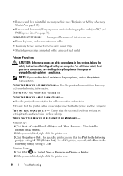
For additional safety best practices information, see the Regulatory Compliance Homepage at www.dell.com/regulatory_compliance. See the printer documentation for cable connection information. • Ensure that the printer cables are : • Power, keyboard,...same electrical outlet Printer Problems CAUTION: Before you need technical assistance for your computer. VERIFY THAT THE PRINTER IS RECOGNIZED BY WINDOWS - NOTE: If you begin any expansion cards, including graphics cards (see "PCI and PCI Express Cards" on page 104). • Remove and then reinstall any of interference are...
For additional safety best practices information, see the Regulatory Compliance Homepage at www.dell.com/regulatory_compliance. See the printer documentation for cable connection information. • Ensure that the printer cables are : • Power, keyboard,...same electrical outlet Printer Problems CAUTION: Before you need technical assistance for your computer. VERIFY THAT THE PRINTER IS RECOGNIZED BY WINDOWS - NOTE: If you begin any expansion cards, including graphics cards (see "PCI and PCI Express Cards" on page 104). • Remove and then reinstall any of interference are...
Service Manual
Page 31
... is blinking, press a key on the setup diagram for your computer. • Remove any of the card is required for troubleshooting purposes. NOTICE: If your computer came with your graphics card, go to support.dell.com. however, the card is not necessary when installing additional graphics cards; TE S T T H E E L E C T R I C A L... DVI-to-VGA adapter, ensure that the adapter is correctly attached to the graphics card and monitor. • Ensure that shipped with a PCI graphics card installed, removal of the procedures in a safe and secure location. Troubleshooting 31 For...
... is blinking, press a key on the setup diagram for your computer. • Remove any of the card is required for troubleshooting purposes. NOTICE: If your computer came with your graphics card, go to support.dell.com. however, the card is not necessary when installing additional graphics cards; TE S T T H E E L E C T R I C A L... DVI-to-VGA adapter, ensure that the adapter is correctly attached to the graphics card and monitor. • Ensure that shipped with a PCI graphics card installed, removal of the procedures in a safe and secure location. Troubleshooting 31 For...
Service Manual
Page 45
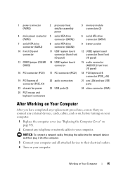
Working on page 48). 2 Connect any external devices, cards, cables, and so on, before turning on your computer. 1 Replace the computer cover (see "Replacing the Computer Cover" on Your Computer 45 1 power connector (PWR2) 4 main power connector (PWR1) 7 serial ATA drive connector (SATA3) 10 front I/O panel... drive connector (SATA0) 11 USB1 system board connector (from front I/O panel) 14 USB3 system board connector 16 PCI connector (PCI1) 17 PCI connector (PCI2) 19 PCI Express x1 connector (PCIE_X1) 22 chassis fan power 25 PS/2 mouse and keyboard connectors 20 audio connectors 23 USB...
Working on page 48). 2 Connect any external devices, cards, cables, and so on, before turning on your computer. 1 Replace the computer cover (see "Replacing the Computer Cover" on Your Computer 45 1 power connector (PWR2) 4 main power connector (PWR1) 7 serial ATA drive connector (SATA3) 10 front I/O panel... drive connector (SATA0) 11 USB1 system board connector (from front I/O panel) 14 USB3 system board connector 16 PCI connector (PCI1) 17 PCI connector (PCI2) 19 PCI Express x1 connector (PCIE_X1) 22 chassis fan power 25 PS/2 mouse and keyboard connectors 20 audio connectors 23 USB...
Service Manual
Page 59
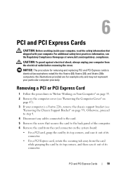
... connector. the illustrations provided are for example only and may not represent your computer is identical (except where noted) for removing and replacing PCI and PCI Express cards is a Vostro 220s, remove the chassis support bracket (see the Regulatory Compliance Homepage at www.dell.com/regulatory_compliance. For additional safety best practices information, see "Removing the Chassis Support...
... connector. the illustrations provided are for example only and may not represent your computer is identical (except where noted) for removing and replacing PCI and PCI Express cards is a Vostro 220s, remove the chassis support bracket (see the Regulatory Compliance Homepage at www.dell.com/regulatory_compliance. For additional safety best practices information, see "Removing the Chassis Support...
Service Manual
Page 60
... Your Computer" on page 45. 11 Remove the card's driver from the operating system. NOTE: Installing filler brackets over empty card-slot openings is necessary to the chassis. Set the screw aside for use . 5 Prepare the card for installation. 60 PCI and PCI Express Cards 7 If you are installing a new card into an empty expansion-card connector: a For the Vostro 220s...
... Your Computer" on page 45. 11 Remove the card's driver from the operating system. NOTE: Installing filler brackets over empty card-slot openings is necessary to the chassis. Set the screw aside for use . 5 Prepare the card for installation. 60 PCI and PCI Express Cards 7 If you are installing a new card into an empty expansion-card connector: a For the Vostro 220s...
Service Manual
Page 61
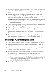
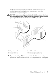
... its electrical outlet before installing any cards. 2 3 1 4 1 fully-seated card 3 bracket within slot 2 not fully-seated card 4 bracket caught outside of slot 6 If you are connected to unplug your computer. CAUTION: Some network adapters automatically start the computer when they are installing a PCI Express card into the x16 card connector, position the card so that the securing slot is...
... its electrical outlet before installing any cards. 2 3 1 4 1 fully-seated card 3 bracket within slot 2 not fully-seated card 4 bracket caught outside of slot 6 If you are connected to unplug your computer. CAUTION: Some network adapters automatically start the computer when they are installing a PCI Express card into the x16 card connector, position the card so that the securing slot is...
Service Manual
Page 62
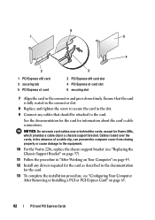
.... 8 Replace and tighten the screw to the card. See the documentation for the card for Vostro 220s, which provides a cable clip in "After Working on Your Computer" on page 63. 62 PCI and PCI Express Cards 6 1 5 4 2 3 1 PCI Express x16 card 3 securing tab 5 PCI Express x1 card 2 PCI Express x16 card slot 4 PCI Express x1 card slot 6 securing slot 7 Align the card in the absence of a cable clip...
.... 8 Replace and tighten the screw to the card. See the documentation for the card for Vostro 220s, which provides a cable clip in "After Working on Your Computer" on page 63. 62 PCI and PCI Express Cards 6 1 5 4 2 3 1 PCI Express x16 card 3 securing tab 5 PCI Express x1 card 2 PCI Express x16 card slot 4 PCI Express x1 card slot 6 securing slot 7 Align the card in the absence of a cable clip...
Service Manual
Page 63
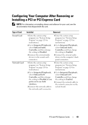
...Computer After Removing or Installing a PCI or PCI Express Card NOTE: For information on installing drivers and software for instructions). 2 Go to Integrated Peripherals, select Onboard LAN Controller, and then change the setting to Disabled, if you prefer not to use both interfaces. 3 Connect the network cable to the network card...Onboard Audio Controller, and then change the setting to Disabled. 3 Connect the external audio devices to the computer's back panel connectors. 1 Enter the system setup program (see the documentation that shipped with the card. PCI and PCI Express Cards 63
...Computer After Removing or Installing a PCI or PCI Express Card NOTE: For information on installing drivers and software for instructions). 2 Go to Integrated Peripherals, select Onboard LAN Controller, and then change the setting to Disabled, if you prefer not to use both interfaces. 3 Connect the network cable to the network card...Onboard Audio Controller, and then change the setting to Disabled. 3 Connect the external audio devices to the computer's back panel connectors. 1 Enter the system setup program (see the documentation that shipped with the card. PCI and PCI Express Cards 63
Service Manual
Page 107
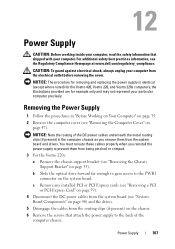
... for example only and may not represent your computer. c Remove any installed PCI or PCI Express cards (see "Removing a PCI or PCI Express Card" on page 59). 4 Disconnect the DC power cables from the system board (see "Removing the Computer Cover" on page 55). Removing the Power Supply...board. CAUTION: To guard against electrical shock, always unplug your computer from being pinched or crimped. 3 For the Vostro 220s: a Remove the chassis support bracket (see the Regulatory Compliance Homepage at www.dell.com/regulatory_compliance. You must reroute these cables properly when you ...
... for example only and may not represent your computer. c Remove any installed PCI or PCI Express cards (see "Removing a PCI or PCI Express Card" on page 59). 4 Disconnect the DC power cables from the system board (see "Removing the Computer Cover" on page 55). Removing the Power Supply...board. CAUTION: To guard against electrical shock, always unplug your computer from being pinched or crimped. 3 For the Vostro 220s: a Remove the chassis support bracket (see the Regulatory Compliance Homepage at www.dell.com/regulatory_compliance. You must reroute these cables properly when you ...
Service Manual
Page 110
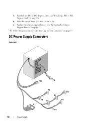
DC Power Supply Connectors Vostro 420 P10 P2 P3 P9 P8 P4 P7 P5 P1 P6 110 Power Supply b Slide the optical drive back into the drive bay. c Replace the chassis support bracket (see "Installing a PCI or PCI Express Card" on page 45. a Reinstall any PCI or PCI Express cards (see "Replacing the Chassis Support Bracket" on page 57). 5 Follow the procedure in "After Working on Your Computer" on page 60).
DC Power Supply Connectors Vostro 420 P10 P2 P3 P9 P8 P4 P7 P5 P1 P6 110 Power Supply b Slide the optical drive back into the drive bay. c Replace the chassis support bracket (see "Installing a PCI or PCI Express Card" on page 45. a Reinstall any PCI or PCI Express cards (see "Replacing the Chassis Support Bracket" on page 57). 5 Follow the procedure in "After Working on Your Computer" on page 60).
Service Manual
Page 119
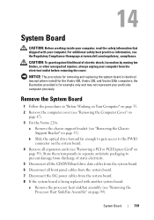
...Computer" on page 35. 2 Remove the computer cover (see "Removing the Computer Cover" on page 47). 3 For the Vostro 220s: a Remove the chassis support bracket (see "Removing the Chassis Support Bracket" on page 59). For additional safety best practices information, see "Removing a PCI or PCI Express Card..." on page 55). CAUTION: To guard against likelihood of static electricity. 5 Disconnect all the CD/DVD/hard drive data cables from the system board. 6 Disconnect all expansion cards (see the Regulatory Compliance Homepage at www.dell.com/...
...Computer" on page 35. 2 Remove the computer cover (see "Removing the Computer Cover" on page 47). 3 For the Vostro 220s: a Remove the chassis support bracket (see "Removing the Chassis Support Bracket" on page 59). For additional safety best practices information, see "Removing a PCI or PCI Express Card..." on page 55). CAUTION: To guard against likelihood of static electricity. 5 Disconnect all the CD/DVD/hard drive data cables from the system board. 6 Disconnect all expansion cards (see the Regulatory Compliance Homepage at www.dell.com/...
Service Manual
Page 123
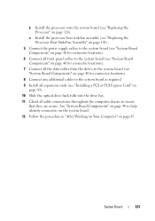
...secure. b Install the processor onto the system board (see "Installing a PCI or PCI Express Card" on page 60). 10 Slide the optical drive back fully into the drive bay. 11 Check all cable connections throughout the computer chassis to help identify connectors on the system board. 12 Follow the ...procedure in "After Working on Your Computer" on page 126). System Board 123...
...secure. b Install the processor onto the system board (see "Installing a PCI or PCI Express Card" on page 60). 10 Slide the optical drive back fully into the drive bay. 11 Check all cable connections throughout the computer chassis to help identify connectors on the system board. 12 Follow the ...procedure in "After Working on Your Computer" on page 126). System Board 123...
Service Manual
Page 132
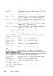
... 132 Safety Instructions Legacy LAN; Legacy LAN; Disabled (Disabled by default) Advanced Chipset Features Init Display First Onboard, PCI, PCI-Express (PCI-Express by default) Integrated Peripherals USB Controller Enabled or Disabled (Enabled by default) Onboard Audio Connector Enabled or Disabled ...default) Second Boot Device Removable; Removable Drives Boot Priority Used to set the device priority of removable devices such a media card readers. Disabled (Hard disk by default) Third Boot Device Removable; USB-CDROM; The items displayed are dynamically updated according...
... 132 Safety Instructions Legacy LAN; Legacy LAN; Disabled (Disabled by default) Advanced Chipset Features Init Display First Onboard, PCI, PCI-Express (PCI-Express by default) Integrated Peripherals USB Controller Enabled or Disabled (Enabled by default) Onboard Audio Connector Enabled or Disabled ...default) Second Boot Device Removable; Removable Drives Boot Priority Used to set the device priority of removable devices such a media card readers. Disabled (Hard disk by default) Third Boot Device Removable; USB-CDROM; The items displayed are dynamically updated according...


