Setup and Quick Reference Guide
Page 4
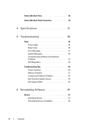
Vostro 220s Back View 28 Vostro 220s Back Panel Connectors 29 4 Specifications 31 5 Troubleshooting 39 Tools 39 Power Lights 39 Beep Codes 39 Error Messages 41 System Messages 46 Troubleshooting Software and Hardware Problems 47 Dell Diagnostics 48 Troubleshooting Tips 50 Power Problems 50 Memory Problems 51 Lockups and Software Problems 52 Dell Technical Update Service 54 Dell Support Utility 55 6 Reinstalling Software 57 Drivers 57 Identifying Drivers 57 Reinstalling Drivers and Utilities 58 4 Contents
Vostro 220s Back View 28 Vostro 220s Back Panel Connectors 29 4 Specifications 31 5 Troubleshooting 39 Tools 39 Power Lights 39 Beep Codes 39 Error Messages 41 System Messages 46 Troubleshooting Software and Hardware Problems 47 Dell Diagnostics 48 Troubleshooting Tips 50 Power Problems 50 Memory Problems 51 Lockups and Software Problems 52 Dell Technical Update Service 54 Dell Support Utility 55 6 Reinstalling Software 57 Drivers 57 Identifying Drivers 57 Reinstalling Drivers and Utilities 58 4 Contents
Setup and Quick Reference Guide
Page 24
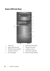
Vostro 220 Front View 1 2 3 4 5 10 6 7 8 9 1 optical drive 3 optional optical-drive bay 5 IEEE 1394 connector (optional) 7 microphone connector 9 drive-activity light 2 drive bay front panel (open) 4 USB 2.0 connectors (4) 6 headphone connector 8 power button, power light 10 media card reader (optional) 24 About Your Computer
Vostro 220 Front View 1 2 3 4 5 10 6 7 8 9 1 optical drive 3 optional optical-drive bay 5 IEEE 1394 connector (optional) 7 microphone connector 9 drive-activity light 2 drive bay front panel (open) 4 USB 2.0 connectors (4) 6 headphone connector 8 power button, power light 10 media card reader (optional) 24 About Your Computer
Setup and Quick Reference Guide
Page 25
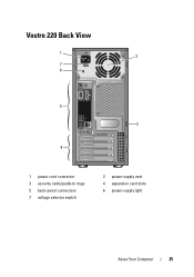
Vostro 220 Back View 1 2 7 6 5 3 4 1 power cord connector 3 security cable/padlock rings 5 back-panel connectors 7 voltage selector switch 2 power-supply vent 4 expansion card slots 6 power-supply light About Your Computer 25
Vostro 220 Back View 1 2 7 6 5 3 4 1 power cord connector 3 security cable/padlock rings 5 back-panel connectors 7 voltage selector switch 2 power-supply vent 4 expansion card slots 6 power-supply light About Your Computer 25
Setup and Quick Reference Guide
Page 27
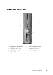
Vostro 220s Front View 1 7 1 media card reader (optional) 3 USB 2.0 connectors (2) 5 microphone connector 7 optical drive 2 3 4 5 6 2 power button, power light 4 headphone connector 6 drive-activity light About Your Computer 27
Vostro 220s Front View 1 7 1 media card reader (optional) 3 USB 2.0 connectors (2) 5 microphone connector 7 optical drive 2 3 4 5 6 2 power button, power light 4 headphone connector 6 drive-activity light About Your Computer 27
Setup and Quick Reference Guide
Page 28
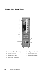
Vostro 220s Back View 1 7 6 2 5 3 4 1 security cable/padlock rings 3 power connector 5 power supply light 7 back-panel connectors 2 voltage selector switch 4 power supply vents 6 expansion card slots 28 About Your Computer
Vostro 220s Back View 1 7 6 2 5 3 4 1 security cable/padlock rings 3 power connector 5 power supply light 7 back-panel connectors 2 voltage selector switch 4 power supply vents 6 expansion card slots 28 About Your Computer

Setup and Quick Reference Guide
Page 36
... exists between the integrated network adapter) network and the computer. Connectors (continued) Front panel audio HDA header Processor Memory Power 12V Power one 10-pin connector one 775-pin connector Vostro 420: four 240-pin connectors Vostro 220/220s: two 240-pin connectors one 4-pin connector one 24...-pin connector Controls and Lights Front of computer: Link integrity light (on green ...
... exists between the integrated network adapter) network and the computer. Connectors (continued) Front panel audio HDA header Processor Memory Power 12V Power one 10-pin connector one 775-pin connector Vostro 420: four 240-pin connectors Vostro 220/220s: two 240-pin connectors one 4-pin connector one 24...-pin connector Controls and Lights Front of computer: Link integrity light (on green ...
Setup and Quick Reference Guide
Page 37
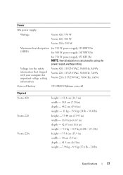
... the safety information that shipped with your computer for 250 W power supply, 853 BTU/hr NOTE: Heat dissipation is calculated by using the power supply wattage rating. Power DC power supply: Wattage Vostro 420: 350 W Vostro 220: 300 W Vostro 220s: 250 W Maximum heat dissipation for 350 W power supply, 1194 BTU/hr (MHD) for 300 W power supply, 1023 BTU/hr for important voltage...
... the safety information that shipped with your computer for 250 W power supply, 853 BTU/hr NOTE: Heat dissipation is calculated by using the power supply wattage rating. Power DC power supply: Wattage Vostro 420: 350 W Vostro 220: 300 W Vostro 220s: 250 W Maximum heat dissipation for 350 W power supply, 1194 BTU/hr (MHD) for 300 W power supply, 1023 BTU/hr for important voltage...
Setup and Features Information Tech Sheet
Page 1
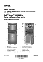
About Warnings WARNING: A WARNING indicates a potential for property damage, personal injury, or death. Dell™ Vostro™ 420/220/220s Setup and Features Information Vostro 420 Front and Back View 1 15 2 14 16 13 3 10 4 9 12 8 7 17 5 11 6 1 optical drive 3 optional optical-drive bays (2) 5 power button, power light 7 microphone connector 9 IEEE 1394 connector (optional) 2 drive bay front panel (open) 4 media card reader (optional) 6 drive-activity light 8 headphone connector 10 USB 2.0 connectors (4) January 2009 Models: DCSCLF, DCSCMF, DCSCSF
About Warnings WARNING: A WARNING indicates a potential for property damage, personal injury, or death. Dell™ Vostro™ 420/220/220s Setup and Features Information Vostro 420 Front and Back View 1 15 2 14 16 13 3 10 4 9 12 8 7 17 5 11 6 1 optical drive 3 optional optical-drive bays (2) 5 power button, power light 7 microphone connector 9 IEEE 1394 connector (optional) 2 drive bay front panel (open) 4 media card reader (optional) 6 drive-activity light 8 headphone connector 10 USB 2.0 connectors (4) January 2009 Models: DCSCLF, DCSCMF, DCSCSF
Setup and Features Information Tech Sheet
Page 2
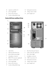
...-panel connectors 14 voltage selector switch 16 power-supply vent Vostro 220 Front and Back View 1 2 15 14 16 10 13 3 9 4 8 12 7 17 5 6 11 1 optical drive 3 optional optical-drive bay 5 power button, power light 7 microphone connector 9 IEEE 1394 connector (optional) 11 expansion card slots (8) 13 power-supply light 15 power cord connector 17 security cable/padlock rings...
...-panel connectors 14 voltage selector switch 16 power-supply vent Vostro 220 Front and Back View 1 2 15 14 16 10 13 3 9 4 8 12 7 17 5 6 11 1 optical drive 3 optional optical-drive bay 5 power button, power light 7 microphone connector 9 IEEE 1394 connector (optional) 11 expansion card slots (8) 13 power-supply light 15 power cord connector 17 security cable/padlock rings...
Setup and Features Information Tech Sheet
Page 3
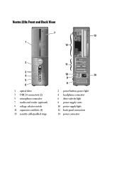
Vostro 220s Front and Back View 7 13 1 12 2 3 4 5 6 1 optical drive 3 USB 2.0 connectors (2) 5 microphone connector 7 media card reader (optional) 9 voltage selector switch 11 expansion card slots (4) 13 security cable/padlock rings 11 10 14 9 8 2 power button, power light 4 headphone connector 6 drive-activity light 8 power supply vents 10 power supply light 12 back-panel connectors 14 power connector
Vostro 220s Front and Back View 7 13 1 12 2 3 4 5 6 1 optical drive 3 USB 2.0 connectors (2) 5 microphone connector 7 media card reader (optional) 9 voltage selector switch 11 expansion card slots (4) 13 security cable/padlock rings 11 10 14 9 8 2 power button, power light 4 headphone connector 6 drive-activity light 8 power supply vents 10 power supply light 12 back-panel connectors 14 power connector
Setup and Features Information Tech Sheet
Page 8
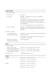
... cell Physical Height Width Vostro 420 - 41.4 cm (16.3 inches) Vostro 220 - 35.44 cm (13.95 inches) Vostro 220s - 35.4 cm (13.9 inches) Vostro 420 - 18.3 cm (7.20 inches) Vostro 220 - 16.94 cm (6.67 inches) Vostro 220s - 10 cm (3.9 inches) Blinking amber indicates a power problem sensed by the power supply unit. A blinking blue light indicates the computer is in sleep state...
... cell Physical Height Width Vostro 420 - 41.4 cm (16.3 inches) Vostro 220 - 35.44 cm (13.95 inches) Vostro 220s - 35.4 cm (13.9 inches) Vostro 420 - 18.3 cm (7.20 inches) Vostro 220 - 16.94 cm (6.67 inches) Vostro 220s - 10 cm (3.9 inches) Blinking amber indicates a power problem sensed by the power supply unit. A blinking blue light indicates the computer is in sleep state...
Service Manual
Page 38
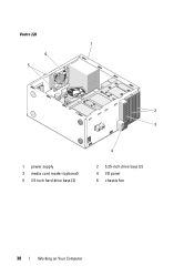
Vostro 220 1 6 5 2 3 1 power supply 3 media card reader (optional) 5 3.5-inch hard drive bays (2) 4 2 5.25-inch drive bays (2) 4 I/O panel 6 chassis fan 38 Working on Your Computer
Vostro 220 1 6 5 2 3 1 power supply 3 media card reader (optional) 5 3.5-inch hard drive bays (2) 4 2 5.25-inch drive bays (2) 4 I/O panel 6 chassis fan 38 Working on Your Computer
Service Manual
Page 39
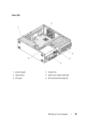
Vostro 220s 2 1 6 ' 1 power supply 3 optical drive 5 I/O panel 3 4 5 2 chassis fan 4 media card reader (optional) 6 3.5-inch hard drive bays (2) Working on Your Computer 39
Vostro 220s 2 1 6 ' 1 power supply 3 optical drive 5 I/O panel 3 4 5 2 chassis fan 4 media card reader (optional) 6 3.5-inch hard drive bays (2) Working on Your Computer 39
Service Manual
Page 65
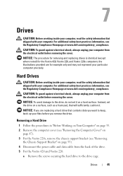
...want to the drive cage. CAUTION: To guard against electrical shock, always unplug your computer. For additional safety best practices information, see the Regulatory Compliance Homepage at www.dell.com/regulatory_compliance. Instead, set it on a surface, such as a foam pad, ... Disconnect the power cable and data cable from the electrical outlet before you are for the Vostro 420, Vostro 220, and Vostro 220s computers; the illustrations provided are replacing a hard drive that shipped with your computer from the back of the drive. 5 For the Vostro 420 and Vostro 220: a Remove ...
...want to the drive cage. CAUTION: To guard against electrical shock, always unplug your computer. For additional safety best practices information, see the Regulatory Compliance Homepage at www.dell.com/regulatory_compliance. Instead, set it on a surface, such as a foam pad, ... Disconnect the power cable and data cable from the electrical outlet before you are for the Vostro 420, Vostro 220, and Vostro 220s computers; the illustrations provided are replacing a hard drive that shipped with your computer from the back of the drive. 5 For the Vostro 420 and Vostro 220: a Remove ...
Service Manual
Page 67
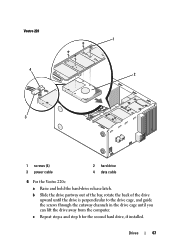
b Slide the drive partway out of the bay, rotate the back of the drive upward until the drive is perpendicular to the drive cage, and guide the screws through the cutaway channels in the drive cage until you can lift the drive away from the computer. c Repeat step a and step b for the second hard drive, if installed. Vostro 220 4 3 1 2 1 screws (4) 3 power cable 2 hard drive 4 data cable 6 For the Vostro 220s: a Raise and hold the hard-drive release latch. Drives 67
b Slide the drive partway out of the bay, rotate the back of the drive upward until the drive is perpendicular to the drive cage, and guide the screws through the cutaway channels in the drive cage until you can lift the drive away from the computer. c Repeat step a and step b for the second hard drive, if installed. Vostro 220 4 3 1 2 1 screws (4) 3 power cable 2 hard drive 4 data cable 6 For the Vostro 220s: a Raise and hold the hard-drive release latch. Drives 67
Service Manual
Page 68
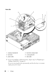
If you are removing this drive permanently and the drive bay is to remain empty, proceed to step 3 in "Replacing or Adding a Hard Drive" on page 69. Vostro 220s 3 2 1 4 56 1 cutaway channels (2) 3 hard drive 5 power cable 2 hard-drive release latch 4 screw guides (4) 6 data cable 7 If you are installing a replacement drive, skip to step 8. 68 Drives
If you are removing this drive permanently and the drive bay is to remain empty, proceed to step 3 in "Replacing or Adding a Hard Drive" on page 69. Vostro 220s 3 2 1 4 56 1 cutaway channels (2) 3 hard drive 5 power cable 2 hard-drive release latch 4 screw guides (4) 6 data cable 7 If you are installing a replacement drive, skip to step 8. 68 Drives
Service Manual
Page 72
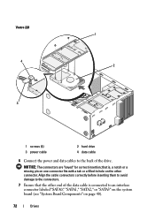
NOTICE: The connectors are "keyed" for correct insertion; Vostro 220 4 3 1 2 1 screws (4) 3 power cable 2 hard drive 4 data cable 6 Connect the power and data cables to an interface connector labeled "SATA0," "SATA1," "SATA2," or "SATA3" on the system board (see "System Board Components" on the other end ...
NOTICE: The connectors are "keyed" for correct insertion; Vostro 220 4 3 1 2 1 screws (4) 3 power cable 2 hard drive 4 data cable 6 Connect the power and data cables to an interface connector labeled "SATA0," "SATA1," "SATA2," or "SATA3" on the system board (see "System Board Components" on the other end ...

Service Manual
Page 81
1 2 5 4 3 1 screws (2) 3 optical drive 5 power cable 2 screw holes (4) 4 data cable 5 For the Vostro 420 and Vostro 220, remove the two screws securing the optical drive to step 5 in "Replacing or Adding an Optical Drive" on page 40), and remove the cable from ... the drive bay is to remain empty, proceed to step 8. 8 Disconnect the data cable from the computer. 9 For the Vostro 420 and Vostro 220, use two screws to attach a 5.25-inch front-panel insert to the front of the computer. 7 If you are installing a replacement drive, skip to the drive cage. 6 Slide the optical drive...
1 2 5 4 3 1 screws (2) 3 optical drive 5 power cable 2 screw holes (4) 4 data cable 5 For the Vostro 420 and Vostro 220, remove the two screws securing the optical drive to step 5 in "Replacing or Adding an Optical Drive" on page 40), and remove the cable from ... the drive bay is to remain empty, proceed to step 8. 8 Disconnect the data cable from the computer. 9 For the Vostro 420 and Vostro 220, use two screws to attach a 5.25-inch front-panel insert to the front of the computer. 7 If you are installing a replacement drive, skip to the drive cage. 6 Slide the optical drive...
Service Manual
Page 83
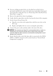
... power cable and data cable to the SATA4, SATA5, or SATA6 connector on the system board (see "Removing a Drive Bay Break-Away Metal Plate" on page 85). 5 Remove the optical drive from its packaging. 6 Gently slide the optical drive into the bay from the front of the computer. 7 For the Vostro 420 and Vostro 220...
... power cable and data cable to the SATA4, SATA5, or SATA6 connector on the system board (see "Removing a Drive Bay Break-Away Metal Plate" on page 85). 5 Remove the optical drive from its packaging. 6 Gently slide the optical drive into the bay from the front of the computer. 7 For the Vostro 420 and Vostro 220...
Service Manual
Page 107
... 47). the illustrations provided are for the Vostro 420, Vostro 220, and Vostro 220s computers; b Slide the optical drive forward far enough to gain access to the back of the DC power cables underneath the metal routing clips (if ...Computer Cover" on page 55). You must reroute these cables properly when you remove them from the electrical outlet before removing the cover. CAUTION: To guard against electrical shock, always unplug your computer from being pinched or crimped. 3 For the Vostro 220s: a Remove the chassis support bracket (see the Regulatory Compliance Homepage at www.dell...
... 47). the illustrations provided are for the Vostro 420, Vostro 220, and Vostro 220s computers; b Slide the optical drive forward far enough to gain access to the back of the DC power cables underneath the metal routing clips (if ...Computer Cover" on page 55). You must reroute these cables properly when you remove them from the electrical outlet before removing the cover. CAUTION: To guard against electrical shock, always unplug your computer from being pinched or crimped. 3 For the Vostro 220s: a Remove the chassis support bracket (see the Regulatory Compliance Homepage at www.dell...


