Setup and Features Information Tech Sheet
Page 2
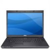
1 display 2 3 device status lights 4 5 media controls (volume, forward, 6 reverse, stop, play, and eject) 7 AC adapter connector 8 9 wireless switch 10 11 fingerprint reader (optional) 12 13 touch pad buttons (2) power button keyboard status lights keyboard USB connectors (2) optical drive/media bay touch pad 10 1 8-in-1 card reader slot 3 audio connectors (2) 5 cooling vents 7 security cable slot 9 video connector 9 87 5 6 2 ExpressCard/54 slot 4 IEEE 1394 connector 6 USB connector 8 network connector 10 battery 3 21 4
1 display 2 3 device status lights 4 5 media controls (volume, forward, 6 reverse, stop, play, and eject) 7 AC adapter connector 8 9 wireless switch 10 11 fingerprint reader (optional) 12 13 touch pad buttons (2) power button keyboard status lights keyboard USB connectors (2) optical drive/media bay touch pad 10 1 8-in-1 card reader slot 3 audio connectors (2) 5 cooling vents 7 security cable slot 9 video connector 9 87 5 6 2 ExpressCard/54 slot 4 IEEE 1394 connector 6 USB connector 8 network connector 10 battery 3 21 4
Setup and Features Information Tech Sheet
Page 4
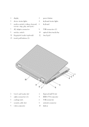
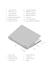
7 security cable slot 9 USB connectors (2) 7 security cable slot 9 USB connectors (2) 11 fingerprint reader (optional) 13 touch pad buttons (2) 15 audio connectors (2) 8 optical drive/media bay 10 IEEE 1394 connector 8 optical drive/media bay 10 IEEE 1394 connector 12 touch pad 14 8-in-1 card reader slot 16 power and battery charge lights 8 7 4 65 1 wireless switch 3 USB connectors (2) 5 AC adapter connector 7 video connector 2 ExpressCard/54 slot 4 cooling vents 6 network connector 8 battery 1 2 3
7 security cable slot 9 USB connectors (2) 7 security cable slot 9 USB connectors (2) 11 fingerprint reader (optional) 13 touch pad buttons (2) 15 audio connectors (2) 8 optical drive/media bay 10 IEEE 1394 connector 8 optical drive/media bay 10 IEEE 1394 connector 12 touch pad 14 8-in-1 card reader slot 16 power and battery charge lights 8 7 4 65 1 wireless switch 3 USB connectors (2) 5 AC adapter connector 7 video connector 2 ExpressCard/54 slot 4 cooling vents 6 network connector 8 battery 1 2 3
Service Manual
Page 31
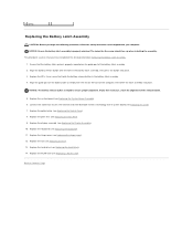
... Replacing the Keyboard). 11. Ensure that the battery latch spring is keyed to Contents Page Replace the keyboard (see Replacing the Hard Drive). 14. The indent for the screw should face up when installing the assembly. Connect the cable that shipped with your computer. Replace the system board (... on the battery latch assembly with the hole in the battery latch assembly. 4. Back to ensure proper alignment. Align the battery release button with the slot on the guide post of the battery latch assembly. 2. NOTICE: Ensure the battery latch assembly is properly oriented.
... Replacing the Keyboard). 11. Ensure that the battery latch spring is keyed to Contents Page Replace the keyboard (see Replacing the Hard Drive). 14. The indent for the screw should face up when installing the assembly. Connect the cable that shipped with your computer. Replace the system board (... on the battery latch assembly with the hole in the battery latch assembly. 4. Back to ensure proper alignment. Align the battery release button with the slot on the guide post of the battery latch assembly. 2. NOTICE: Ensure the battery latch assembly is properly oriented.
Service Manual
Page 38
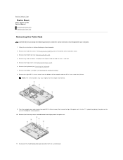
Follow the instructions in - 1 card slot. 5. Remove the hard drive cover. Remove the three cap screws located towards the display end of the hard drive cover. 3. Remove the hinge cover (see Removing the Keyboard). 7. Turn the computer over and remove the eight M2.5 x 5-mm screws that...Assembly). 8. See Removing the Hard Drive for an illustration of the palm rest. 11. Remove any cards or blanks installed in the ExpressCard slot and the 8-in Before Working on the palm rest to Contents Page Palm Rest Dell™ Vostro™ 1710 Service Manual Removing the Palm Rest ...
Follow the instructions in - 1 card slot. 5. Remove the hard drive cover. Remove the three cap screws located towards the display end of the hard drive cover. 3. Remove the hinge cover (see Removing the Keyboard). 7. Turn the computer over and remove the eight M2.5 x 5-mm screws that...Assembly). 8. See Removing the Hard Drive for an illustration of the palm rest. 11. Remove any cards or blanks installed in the ExpressCard slot and the 8-in Before Working on the palm rest to Contents Page Palm Rest Dell™ Vostro™ 1710 Service Manual Removing the Palm Rest ...

Service Manual
Page 40
in the ExpressCard slot and the 8- 12. Replace any blanks you removed from in -1 card slot. Replace the hard drive cover. See Removing the Hard Drive for an illustration of the hard drive cover. 13. Back to Contents Page
in the ExpressCard slot and the 8- 12. Replace any blanks you removed from in -1 card slot. Replace the hard drive cover. See Removing the Hard Drive for an illustration of the hard drive cover. 13. Back to Contents Page

Service Manual
Page 45
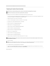
...Remove the display assembly (see Removing the Hard Drive). 4. Remove the two M2.5 x 5-mm screws from the system board. 12. The replacement kit for transferring the Service Tag to Contents Page System Board Assembly Dell™ Vostro™ 1710 Service Manual Removing the System Board Assembly Replacing ... Your Computer. 2. Remove the hard drive (see Removing the Display Assembly). 9. Remove the fan (see Removing the Palm Rest). 10. Remove the palm rest (see Removing the Fan). 6. Remove any cards or blanks installed in the ExpressCard slot and the 8-in Before Working on ...
...Remove the display assembly (see Removing the Hard Drive). 4. Remove the two M2.5 x 5-mm screws from the system board. 12. The replacement kit for transferring the Service Tag to Contents Page System Board Assembly Dell™ Vostro™ 1710 Service Manual Removing the System Board Assembly Replacing ... Your Computer. 2. Remove the hard drive (see Removing the Display Assembly). 9. Remove the fan (see Removing the Palm Rest). 10. Remove the palm rest (see Removing the Fan). 6. Remove any cards or blanks installed in the ExpressCard slot and the 8-in Before Working on ...
Service Manual
Page 46
...base of the computer, then carefully lower the system board into the base of the computer at support.dell.com. Replace the hinge cover (see Replacing the Hard Drive). 13. Replace the hard drive (see Replacing the Hinge Cover). 10. Failure to do not get caught beneath the system board.... the DC-in cable and speaker cable from the ExpressCard slot and the 8-in damage to boot from the media for more information). 16. Flash update the BIOS (see Replacing the Optical Drive). 6. Replace the WLAN card (see the Dell™ Technology Guide on your computer or at an angle...
...base of the computer, then carefully lower the system board into the base of the computer at support.dell.com. Replace the hinge cover (see Replacing the Hard Drive). 13. Replace the hard drive (see Replacing the Hinge Cover). 10. Failure to do not get caught beneath the system board.... the DC-in cable and speaker cable from the ExpressCard slot and the 8-in damage to boot from the media for more information). 16. Flash update the BIOS (see Replacing the Optical Drive). 6. Replace the WLAN card (see the Dell™ Technology Guide on your computer or at an angle...


