Setup and Quick Reference Guide
Page 25
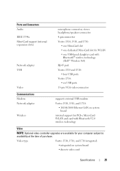
... Bluetooth V2.0 wireless technology Video NOTE: Optional video controller upgrades are available for WLAN • one USB-based daughter card with Bluetooth® wireless technology (Dell™ Wireless 360) RJ-45 port Vostro 1310 and 1510: • four USB ports Vostro 1710: • six USB ports 15-pin VGA video connector Communications Modem Network adapter...
... Bluetooth V2.0 wireless technology Video NOTE: Optional video controller upgrades are available for WLAN • one USB-based daughter card with Bluetooth® wireless technology (Dell™ Wireless 360) RJ-45 port Vostro 1310 and 1510: • four USB ports Vostro 1710: • six USB ports 15-pin VGA video connector Communications Modem Network adapter...

Service Manual
Page 1
...other than its own. Other trademarks and trade names may be used in any proprietary interest in this text: Dell, the DELL logo, and Vostro are either the entities claiming the marks and names or their products. Bluetooth is strictly forbidden. Microsoft, Windows,... Windows Vista, and the Windows start button logo are trademarks of Dell Inc. A01 Dell™ Vostro™ 1710 Service Manual Troubleshooting Before Working on Your Computer Hard Drive Wireless Local Area Network (WLAN) Card Fan Processor Thermal-Cooling Assembly Processor Module Memory Hinge Cover Keyboard...
...other than its own. Other trademarks and trade names may be used in any proprietary interest in this text: Dell, the DELL logo, and Vostro are either the entities claiming the marks and names or their products. Bluetooth is strictly forbidden. Microsoft, Windows,... Windows Vista, and the Windows start button logo are trademarks of Dell Inc. A01 Dell™ Vostro™ 1710 Service Manual Troubleshooting Before Working on Your Computer Hard Drive Wireless Local Area Network (WLAN) Card Fan Processor Thermal-Cooling Assembly Processor Module Memory Hinge Cover Keyboard...
Service Manual
Page 7
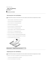
... the safety instructions that shipped with your computer. 1. Connect the coin-cell battery cable to Contents Page Coin-Cell Battery Dell™ Vostro™ 1710 Service Manual Removing the Coin-Cell Battery Replacing the Coin-Cell Battery Removing the Coin-Cell Battery CAUTION: Before you begin any...see Removing the Optical Drive). 10. Position the coin-cell battery on Your Computer. 2. Remove the optical drive (see Removing a WLAN Card). 4. This procedure assumes that you have completed the removal procedure Removing the Coin-Cell Battery. 1. Remove the system board (see...
... the safety instructions that shipped with your computer. 1. Connect the coin-cell battery cable to Contents Page Coin-Cell Battery Dell™ Vostro™ 1710 Service Manual Removing the Coin-Cell Battery Replacing the Coin-Cell Battery Removing the Coin-Cell Battery CAUTION: Before you begin any...see Removing the Optical Drive). 10. Position the coin-cell battery on Your Computer. 2. Remove the optical drive (see Removing a WLAN Card). 4. This procedure assumes that you have completed the removal procedure Removing the Coin-Cell Battery. 1. Remove the system board (see...
Service Manual
Page 8
Replace the WLAN card (see Replacing the Fan). 10. Back to Contents Page Replace the fan (see Replacing a WLAN Card). 11. Replace the keyboard (see Replacing the Hard Drive). Replace the hard drive (see Replacing the Keyboard). 8. Replace the display assembly (see Replacing the Palm Rest). 6. Replace the palm rest (see Replacing the Display Assembly). 7. Replace the hinge cover (see Replacing the System Board Assembly). 4. 3. Replace the system board (see Replacing the Hinge Cover). 9. Replace the optical drive (see Replacing the Optical Drive). 5.
Replace the WLAN card (see Replacing the Fan). 10. Back to Contents Page Replace the fan (see Replacing a WLAN Card). 11. Replace the keyboard (see Replacing the Hard Drive). Replace the hard drive (see Replacing the Keyboard). 8. Replace the display assembly (see Replacing the Palm Rest). 6. Replace the palm rest (see Replacing the Display Assembly). 7. Replace the hinge cover (see Replacing the System Board Assembly). 4. 3. Replace the system board (see Replacing the Hinge Cover). 9. Replace the optical drive (see Replacing the Optical Drive). 5.
Service Manual
Page 12
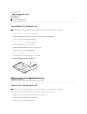
...Hard Drive for an illustration of the hard drive cover. 3. Remove the hard drive cover. Remove the WLAN card (see Removing the Keyboard). 6. Remove the keyboard (see Removing a WLAN Card). 4. This procedure assumes that you begin the following procedure, follow the safety instructions that shipped ...the Hinge Cover). 5. Connect the daughter card connector to the computer base. 2. Back to Contents Page USB Daughter Card Dell™ Vostro™ 1710 Service Manual Removing the USB Daughter Card Replacing the USB Daughter Card Removing the USB Daughter Card CAUTION: Before you begin ...
...Hard Drive for an illustration of the hard drive cover. 3. Remove the hard drive cover. Remove the WLAN card (see Removing the Keyboard). 6. Remove the keyboard (see Removing a WLAN Card). 4. This procedure assumes that you begin the following procedure, follow the safety instructions that shipped ...the Hinge Cover). 5. Connect the daughter card connector to the computer base. 2. Back to Contents Page USB Daughter Card Dell™ Vostro™ 1710 Service Manual Removing the USB Daughter Card Replacing the USB Daughter Card Removing the USB Daughter Card CAUTION: Before you begin ...
Service Manual
Page 13
Replace the keyboard (see Replacing a WLAN Card). 8. Replace the hard drive cover. Replace the WLAN card (see Replacing the Keyboard). 6. Replace the hinge cover (see Replacing the Display Assembly). 5. Back to Contents Page 4. Replace the display assembly (see Replacing the Hinge Cover). 7. See Removing the Hard Drive for an illustration of the hard drive cover.
Replace the keyboard (see Replacing a WLAN Card). 8. Replace the hard drive cover. Replace the WLAN card (see Replacing the Keyboard). 6. Replace the hinge cover (see Replacing the Display Assembly). 5. Back to Contents Page 4. Replace the display assembly (see Replacing the Hinge Cover). 7. See Removing the Hard Drive for an illustration of the hard drive cover.
Service Manual
Page 14
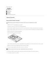
... facing bottom side up, remove the two M2.5 x 8-mm screws that attach the display assembly to Contents Page Display Dell™ Vostro™ 1710 Service Manual Display Assembly Display Bezel Display Panel Display Cable Camera and Microphone Assembly Display Assembly Removing the Display Assembly CAUTION: Before..., remove in Before Working on the system board. Follow the instructions in sequential order the three numbered M2.5 x 5-mm screws from the WLAN card (see Removing the Keyboard). 7. Remove the hinge cover (see Removing the Hinge Cover). 6. Back to both corners of the display ...
... facing bottom side up, remove the two M2.5 x 8-mm screws that attach the display assembly to Contents Page Display Dell™ Vostro™ 1710 Service Manual Display Assembly Display Bezel Display Panel Display Cable Camera and Microphone Assembly Display Assembly Removing the Display Assembly CAUTION: Before..., remove in Before Working on the system board. Follow the instructions in sequential order the three numbered M2.5 x 5-mm screws from the WLAN card (see Removing the Keyboard). 7. Remove the hinge cover (see Removing the Hinge Cover). 6. Back to both corners of the display ...
Service Manual
Page 15
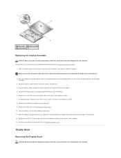
... Display Assembly. 1. Align the display hinges with the holes in sequential order the three numbered M2.5 x 5-mm screws that secures the display cable to the WLAN card (see Replacing...
... Display Assembly. 1. Align the display hinges with the holes in sequential order the three numbered M2.5 x 5-mm screws that secures the display cable to the WLAN card (see Replacing...
Service Manual
Page 16
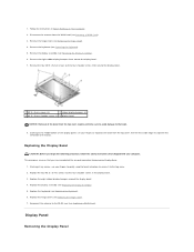
...cover (see Replacing the Display Assembly). 5. Replace the eight rubber display bumpers around the display bezel. 7. Replace the keyboard (see Removing a WLAN Card). 3. Remove the eight rubber display-bumpers from the top cover requires extreme care to avoid damage to the top cover. 2. This procedure... assumes that shipped with your fingers to separate the bezel from the top cover, then lift the inside edges to the WLAN card (see Removing the Display Assembly). 6. Replacing the Display Bezel CAUTION: Before you begin the following procedure, follow the safety ...
...cover (see Replacing the Display Assembly). 5. Replace the eight rubber display bumpers around the display bezel. 7. Replace the keyboard (see Removing a WLAN Card). 3. Remove the eight rubber display-bumpers from the top cover requires extreme care to avoid damage to the top cover. 2. This procedure... assumes that shipped with your fingers to separate the bezel from the top cover, then lift the inside edges to the WLAN card (see Removing the Display Assembly). 6. Replacing the Display Bezel CAUTION: Before you begin the following procedure, follow the safety ...
Service Manual
Page 17
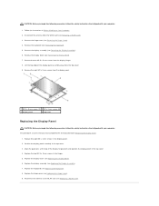
...Replace the display bezel (see Replacing the Display Assembly). 7. Align the guide pins at the top of the display panel assembly away from the WLAN card (see Replacing the Keyboard). 8. Replace the display assembly (see Replacing the Display Bezel). 6. Remove the keyboard (see Replacing... hinge panels and position the display panel in the top cover. 3. Position the display panel assembly in the top cover. 4. Reconnect the antenna to the WLAN card (see Removing the Keyboard). 5. Replace the two M2.5 x 5-mm screws in Before Working on Your Computer. 2. Replace the hinge cover (see...
...Replace the display bezel (see Replacing the Display Assembly). 7. Align the guide pins at the top of the display panel assembly away from the WLAN card (see Replacing the Keyboard). 8. Replace the display assembly (see Replacing the Display Bezel). 6. Remove the keyboard (see Replacing... hinge panels and position the display panel in the top cover. 3. Position the display panel assembly in the top cover. 4. Reconnect the antenna to the WLAN card (see Removing the Keyboard). 5. Replace the two M2.5 x 5-mm screws in Before Working on Your Computer. 2. Replace the hinge cover (see...
Service Manual
Page 18
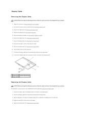
... on the back of the display panel. 12. Disconnect the antenna from the hinges. 9. Remove the display assembly (see Removing a WLAN Card). 3. Remove the two M2.5 x 5-mm screws from the WLAN card (see Removing the Display Assembly). 6. Connect the display cable to the connector on Your Computer. 2. Align the guide pins at...
... on the back of the display panel. 12. Disconnect the antenna from the hinges. 9. Remove the display assembly (see Removing a WLAN Card). 3. Remove the two M2.5 x 5-mm screws from the WLAN card (see Removing the Display Assembly). 6. Connect the display cable to the connector on Your Computer. 2. Align the guide pins at...
Service Manual
Page 19
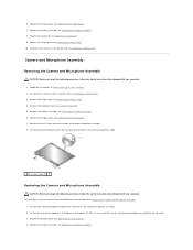
Replace the hinge cover (see Replacing the Display Bezel). 7. Connect the camera/microphone cable to the WLAN card (see Removing the Display Assembly). 6. Replace the display bezel (see Replacing the Hinge Cover). 10. Follow the instructions in the top cover and replace .... 1. Position the camera/microphone in Before Working on the camera/microphone assembly. 2. mm screw that secures the camera/microphone assembly. 8. Disconnect the antenna from the WLAN card (see Replacing the Keyboard). 9. Replace the keyboard (see Removing...
Replace the hinge cover (see Replacing the Display Bezel). 7. Connect the camera/microphone cable to the WLAN card (see Removing the Display Assembly). 6. Replace the display bezel (see Replacing the Hinge Cover). 10. Follow the instructions in the top cover and replace .... 1. Position the camera/microphone in Before Working on the camera/microphone assembly. 2. mm screw that secures the camera/microphone assembly. 8. Disconnect the antenna from the WLAN card (see Replacing the Keyboard). 9. Replace the keyboard (see Removing...

Service Manual
Page 20
Back to the WLAN card (see Replacing the Hinge Cover). 7. Replace the hinge cover (see Replacing a WLAN Card). 5. Reconnect the antenna to Contents Page Replace the keyboard (see Replacing the Keyboard). 6.
Back to the WLAN card (see Replacing the Hinge Cover). 7. Replace the hinge cover (see Replacing a WLAN Card). 5. Reconnect the antenna to Contents Page Replace the keyboard (see Replacing the Keyboard). 6.
Service Manual
Page 22
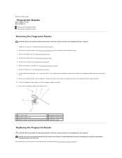
Follow the instructions in Before Working on the palm rest upward to Contents Page Fingerprint Reader Dell™ Vostro™ 1710 Service Manual Removing the Fingerprint Reader Replacing the Fingerprint Reader Removing the Fingerprint Reader CAUTION: Before you begin the ...with Bluetooth® wireless technology are properly routed before snapping the palm rest into place. Remove the WLAN card (see Removing the Hinge Cover). 5. Remove the hinge cover (see Removing a WLAN Card). 4. Rotate the retaining bracket on the fingerprint reader connector on Your Computer. 2. This procedure...
Follow the instructions in Before Working on the palm rest upward to Contents Page Fingerprint Reader Dell™ Vostro™ 1710 Service Manual Removing the Fingerprint Reader Replacing the Fingerprint Reader Removing the Fingerprint Reader CAUTION: Before you begin the ...with Bluetooth® wireless technology are properly routed before snapping the palm rest into place. Remove the WLAN card (see Removing the Hinge Cover). 5. Remove the hinge cover (see Removing a WLAN Card). 4. Rotate the retaining bracket on the fingerprint reader connector on Your Computer. 2. This procedure...
Service Manual
Page 23
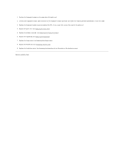
... to Contents Page Replace the display assembly (see Replacing the Palm Rest). 5. Replace the hinge cover (see Replacing a WLAN Card). 9. Replace the hard drive cover. Back to the palm rest. 4. Replace the WLAN card (see Replacing the Hinge Cover). 8. Position the fingerprint reader on the underside of the hard drive cover. 1. Replace...
... to Contents Page Replace the display assembly (see Replacing the Palm Rest). 5. Replace the hinge cover (see Replacing a WLAN Card). 9. Replace the hard drive cover. Back to the palm rest. 4. Replace the WLAN card (see Replacing the Hinge Cover). 8. Position the fingerprint reader on the underside of the hard drive cover. 1. Replace...
Service Manual
Page 30
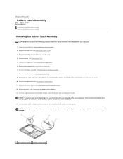
Back to Contents Page Battery Latch Assembly Dell™ Vostro™ 1710 Service Manual Removing the Battery Latch Assembly Replacing the Battery Latch Assembly Removing the Battery Latch Assembly CAUTION: Before you remove the battery release button, ... the button to the latch assembly and can be reinstalled. 14. Remove the keyboard (see Removing a WLAN Card). 4. When removing the battery latch assembly, place the spring in Before Working on Your Computer. 2. Remove the WLAN card (see Removing the Keyboard). 7. Remove the M2 x 3-mm screw from the battery release button. 13...
Back to Contents Page Battery Latch Assembly Dell™ Vostro™ 1710 Service Manual Removing the Battery Latch Assembly Replacing the Battery Latch Assembly Removing the Battery Latch Assembly CAUTION: Before you remove the battery release button, ... the button to the latch assembly and can be reinstalled. 14. Remove the keyboard (see Removing a WLAN Card). 4. When removing the battery latch assembly, place the spring in Before Working on Your Computer. 2. Remove the WLAN card (see Removing the Keyboard). 7. Remove the M2 x 3-mm screw from the battery release button. 13...
Service Manual
Page 31
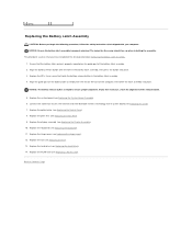
...assembly. 4. Replace the system board (see Replacing the Keyboard). 11. Replace the keyboard (see Replacing the System Board Assembly). 6. Replace the WLAN card (see Replacing the Display Assembly). 10. The indent for the screw should face up when installing the assembly. Ensure that the battery latch...is properly mounted on the base of the computer, then lower the latch assembly into place. 3. Replace the display assembly (see Replacing a WLAN Card). Align the battery release button with the slot on the guide post of the battery latch assembly. 2. Replace the palm rest (...
...assembly. 4. Replace the system board (see Replacing the Keyboard). 11. Replace the keyboard (see Replacing the System Board Assembly). 6. Replace the WLAN card (see Replacing the Display Assembly). 10. The indent for the screw should face up when installing the assembly. Ensure that the battery latch...is properly mounted on the base of the computer, then lower the latch assembly into place. 3. Replace the display assembly (see Replacing a WLAN Card). Align the battery release button with the slot on the guide post of the battery latch assembly. 2. Replace the palm rest (...
Service Manual
Page 34
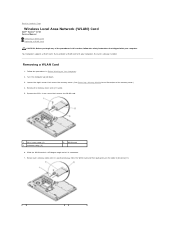
... 1. Rotate each antenna cable until it is positioned away from the WLAN card and then pull gently on the cable to Contents Page Wireless Local Area Network (WLAN) Card Dell™ Vostro™ 1710 Service Manual Removing a WLAN Card Replacing a WLAN Card CAUTION: Before you ordered a WLAN card with your computer, the card is already installed. Back to...
... 1. Rotate each antenna cable until it is positioned away from the WLAN card and then pull gently on the cable to Contents Page Wireless Local Area Network (WLAN) Card Dell™ Vostro™ 1710 Service Manual Removing a WLAN Card Replacing a WLAN Card CAUTION: Before you ordered a WLAN card with your computer, the card is already installed. Back to...

Service Manual
Page 35
...black antenna cable to the black triangle, and connect the gray antenna cable to ensure correct insertion. NOTICE: To avoid damage to the WLAN card that secures the WLAN card. 4. This procedure assumes that secure the memory cover. degree angle. 2. Connect the antenna cables to the... the M2 x 3-mm screw that you have completed the removal procedure Removing a WLAN Card. 1. Back to the connector labeled "aux" (black triangle). Insert the WLAN card connector into the system board connector at a 45- If the WLAN card has two triangles on the label (white and black), connect the white antenna...
...black antenna cable to the black triangle, and connect the gray antenna cable to ensure correct insertion. NOTICE: To avoid damage to the WLAN card that secures the WLAN card. 4. This procedure assumes that secure the memory cover. degree angle. 2. Connect the antenna cables to the... the M2 x 3-mm screw that you have completed the removal procedure Removing a WLAN Card. 1. Back to the connector labeled "aux" (black triangle). Insert the WLAN card connector into the system board connector at a 45- If the WLAN card has two triangles on the label (white and black), connect the white antenna...

Service Manual
Page 36
...Removing the Hinge Cover). 5. Remove the hinge cover (see Replacing the Palm Rest). 4. Replace the display assembly (see Removing a WLAN Card). 4. Remove the WLAN card (see Replacing the Display Assembly). Connect the optical drive cable to the system board. 3. Remove the M2.5 x 5-mm...x 5-mm screw to secure the optical drive to the connector on Your Computer. 2. Back to Contents Page Optical Drive Dell™ Vostro™ 1710 Service Manual Removing the Optical Drive Replacing the Optical Drive Removing the Optical Drive CAUTION: Before you begin any of the ...
...Removing the Hinge Cover). 5. Remove the hinge cover (see Replacing the Palm Rest). 4. Replace the display assembly (see Removing a WLAN Card). 4. Remove the WLAN card (see Replacing the Display Assembly). Connect the optical drive cable to the system board. 3. Remove the M2.5 x 5-mm...x 5-mm screw to secure the optical drive to the connector on Your Computer. 2. Back to Contents Page Optical Drive Dell™ Vostro™ 1710 Service Manual Removing the Optical Drive Replacing the Optical Drive Removing the Optical Drive CAUTION: Before you begin any of the ...


