User Manual
Page 2
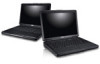
... not store your Dell computer in the air vents. microphone 10. touchpad buttons (2) 13. HDMI connector 8. audio connectors 9. device status lights 14. power connector 4. cooling vents 5. The computer turns on the fan when the computer gets hot. ...
... not store your Dell computer in the air vents. microphone 10. touchpad buttons (2) 13. HDMI connector 8. audio connectors 9. device status lights 14. power connector 4. cooling vents 5. The computer turns on the fan when the computer gets hot. ...
User Manual
Page 3
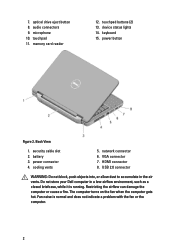
speakers (2) 5. USB 2.0 connectors (2) 8. memory card reader 12. device status lights 13. keyboard 14. Front View 1. optical drive eject button 7. camera status light 2. microphone 11. touchpad 9. Front And Back - camera 3. touchpad buttons (2) 10. power button 3 display 4. Vostro 1540/1550 Figure 3. optical drive 6.
speakers (2) 5. USB 2.0 connectors (2) 8. memory card reader 12. device status lights 13. keyboard 14. Front View 1. optical drive eject button 7. camera status light 2. microphone 11. touchpad 9. Front And Back - camera 3. touchpad buttons (2) 10. power button 3 display 4. Vostro 1540/1550 Figure 3. optical drive 6.
Owners Manual
Page 23
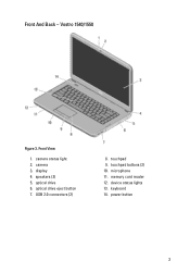
Follow the procedures in Before Working On Your Computer. 2. Remove the keyboard. 4. Removing The Palm Rest 8 1. Flip the computer around and disconnect the power board cable (1) and the touchpad cable (2). 6. Remove the screws that secure the palm rest to the computer. 23 Remove the battery. 3. Remove the screws that secure the bottom base. 5.
Follow the procedures in Before Working On Your Computer. 2. Remove the keyboard. 4. Removing The Palm Rest 8 1. Flip the computer around and disconnect the power board cable (1) and the touchpad cable (2). 6. Remove the screws that secure the palm rest to the computer. 23 Remove the battery. 3. Remove the screws that secure the bottom base. 5.
Owners Manual
Page 25
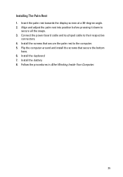
Install the screws that secure the bottom base. 6. Install the battery. 8. Installing The Palm Rest 1. Align and adjust the palm rest into position before pressing it down to their respective connectors. 4. Install the keyboard. 7. Connect the power board cable and touchpad cable to secure all the snaps. 3. Flip the computer around and install the screws that secure the palm rest to the computer. 5. Follow the procedures in After Working Inside Your Computer. 25 Insert the palm rest towards the display screen at a 30-degree angle. 2.
Install the screws that secure the bottom base. 6. Install the battery. 8. Installing The Palm Rest 1. Align and adjust the palm rest into position before pressing it down to their respective connectors. 4. Install the keyboard. 7. Connect the power board cable and touchpad cable to secure all the snaps. 3. Flip the computer around and install the screws that secure the palm rest to the computer. 5. Follow the procedures in After Working Inside Your Computer. 25 Insert the palm rest towards the display screen at a 30-degree angle. 2.

Owners Manual
Page 82
Display Diagonal Active area (X/Y) Maximum resolution Maximum Brightness Operating angle Refresh rate Minimum Viewing angles: Horizontal Vertical Pixel pitch Keyboard Number of keys: Touchpad Active Area: X-axis Y-axis Battery Type Dimensions: Height Width Depth Weight Charge time 82 396.24 mm (15.60 inches) 344.23 mm x 193.54 ...
Display Diagonal Active area (X/Y) Maximum resolution Maximum Brightness Operating angle Refresh rate Minimum Viewing angles: Horizontal Vertical Pixel pitch Keyboard Number of keys: Touchpad Active Area: X-axis Y-axis Battery Type Dimensions: Height Width Depth Weight Charge time 82 396.24 mm (15.60 inches) 344.23 mm x 193.54 ...


