Vostro 15-3568 Owners Manual
Page 3
......14 Removing the battery...14 Installing the battery...14 Optical drive...15 Removing the optical drive ...15 Removing the optical drive bracket...15 Installing the optical drive bracket...16 Installing the optical drive...16 Keyboard lattice and Keyboard...16 Removing the keyboard...16 Installing the keyboard...18 Base cover...18 Removing the base cover...18 Installing the...
......14 Removing the battery...14 Installing the battery...14 Optical drive...15 Removing the optical drive ...15 Removing the optical drive bracket...15 Installing the optical drive bracket...16 Installing the optical drive...16 Keyboard lattice and Keyboard...16 Removing the keyboard...16 Installing the keyboard...18 Base cover...18 Removing the base cover...18 Installing the...
Vostro 15-3568 Owners Manual
Page 5
... ...64 Verifying system memory in setup...64 Testing memory using ePSA...64 Audio drivers...65 Chapter 4: System setup...66 Boot Sequence...66 Navigation keys...66 Keyboards Hot Key Definitions...67 System setup options...67 Updating the BIOS in Windows ...74 System and setup password...75 Assigning a system setup password...75 Deleting...
... ...64 Verifying system memory in setup...64 Testing memory using ePSA...64 Audio drivers...65 Chapter 4: System setup...66 Boot Sequence...66 Navigation keys...66 Keyboards Hot Key Definitions...67 System setup options...67 Updating the BIOS in Windows ...74 System and setup password...75 Assigning a system setup password...75 Deleting...
Vostro 15-3568 Owners Manual
Page 10
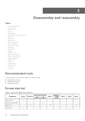
...reassembly Topics: • Recommended tools • Screw size list • Chassis view • Battery • Optical drive • Keyboard lattice and Keyboard • Base cover • Hard drive • WLAN card • Memory modules • Coin-cell battery • Power...this document require the following tools: ● Phillips #0 screwdriver ● Phillips #1 screwdriver ● Small plastic scribe Screw size list Table 1. Vostro 15-3562 screw size list Component M2L3 M2L2(Bi M2L2(Bi M2.5L8 g g head07) head05) Optical drive 1 Optical drive bracket 1 Base Cover...
...reassembly Topics: • Recommended tools • Screw size list • Chassis view • Battery • Optical drive • Keyboard lattice and Keyboard • Base cover • Hard drive • WLAN card • Memory modules • Coin-cell battery • Power...this document require the following tools: ● Phillips #0 screwdriver ● Phillips #1 screwdriver ● Small plastic scribe Screw size list Table 1. Vostro 15-3562 screw size list Component M2L3 M2L2(Bi M2L2(Bi M2.5L8 g g head07) head05) Optical drive 1 Optical drive bracket 1 Base Cover...
Vostro 15-3568 Owners Manual
Page 13
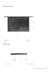
Palm rest Right view 2. Keyboard 4. Palm rest view 1. Power button 3. Touchpad 1. Universal audio port Disassembly and reassembly 13 SD card reader 2.
Palm rest Right view 2. Keyboard 4. Palm rest view 1. Power button 3. Touchpad 1. Universal audio port Disassembly and reassembly 13 SD card reader 2.
Vostro 15-3568 Owners Manual
Page 16
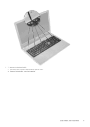
... drive to secure the optical drive bracket. 3. Install the battery. 4. battery 4. Installing the optical drive 1. To remove the keyboard: a. Flip the keyboard on the palm rest to access the keyboard connector cable under the keyboard [2]. 16 Disassembly and reassembly Follow the procedure in Before working inside your computer. Using a plastic scribe, release the five...
... drive to secure the optical drive bracket. 3. Install the battery. 4. battery 4. Installing the optical drive 1. To remove the keyboard: a. Flip the keyboard on the palm rest to access the keyboard connector cable under the keyboard [2]. 16 Disassembly and reassembly Follow the procedure in Before working inside your computer. Using a plastic scribe, release the five...
Vostro 15-3568 Owners Manual
Page 17
b. Disassembly and reassembly 17 To remove the keyboard cable: a. Disconnect the keyboard cable from the computer. Remove the keyboard from the system board. 4.
b. Disassembly and reassembly 17 To remove the keyboard cable: a. Disconnect the keyboard cable from the computer. Remove the keyboard from the system board. 4.
Vostro 15-3568 Owners Manual
Page 18
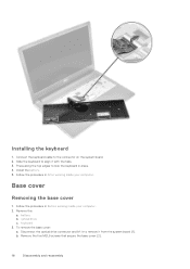
... the base cover 1. Follow the procedure in Before working inside your computer. keyboard 3. Install the battery. 5. To remove the base cover: a. Connect the keyboard cable to align it with the tabs. 3. battery b. Slide the keyboard to the connector on the system board. 2. Follow the procedure in place....[2]. 18 Disassembly and reassembly Remove the: a. b. Press along the top edges to remove it to lock the keyboard in After working inside your computer. 2. Disconnect the optical drive connector and lift it from the system board [1]. Installing the...
... the base cover 1. Follow the procedure in Before working inside your computer. keyboard 3. Install the battery. 5. To remove the base cover: a. Connect the keyboard cable to align it with the tabs. 3. battery b. Slide the keyboard to the connector on the system board. 2. Follow the procedure in place....[2]. 18 Disassembly and reassembly Remove the: a. b. Press along the top edges to remove it to lock the keyboard in After working inside your computer. 2. Disconnect the optical drive connector and lift it from the system board [1]. Installing the...
Vostro 15-3568 Owners Manual
Page 21
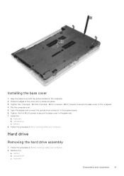
.... 2. battery b. M2L2) screws to secure the base cover to the palm rest. 7. optical drive c. optical drive c. Tighten the ( 8 screws - Flip the computer over. 5. keyboard b. Hard drive Removing the hard drive assembly 1. Follow the procedure in After working inside your computer. 2. Press the edges of the cover until it clicks...battery 8. M2L2; 2 screws- Remove the: a. Installing the base cover 1. M2.5L8; 3 screws - Open the display and connect the optical drive connector to the system board. 6. keyboard Disassembly and reassembly 21 Install the: a.
.... 2. battery b. M2L2) screws to secure the base cover to the palm rest. 7. optical drive c. optical drive c. Tighten the ( 8 screws - Flip the computer over. 5. keyboard b. Hard drive Removing the hard drive assembly 1. Follow the procedure in After working inside your computer. 2. Press the edges of the cover until it clicks...battery 8. M2L2; 2 screws- Remove the: a. Installing the base cover 1. M2.5L8; 3 screws - Open the display and connect the optical drive connector to the system board. 6. keyboard Disassembly and reassembly 21 Install the: a.
Vostro 15-3568 Owners Manual
Page 22
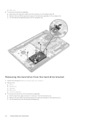
base cover 3. Remove the four M2L3 screws that secure the hard drive bracket to the hard drive [2]. Remove the: a. battery b. optical drive c. keyboard d. Pull the hard drive cable connector to the computer [2]. Remove the four M3L3 screws that secure the hard drive assembly to remove it from the ...
base cover 3. Remove the four M2L3 screws that secure the hard drive bracket to the hard drive [2]. Remove the: a. battery b. optical drive c. keyboard d. Pull the hard drive cable connector to the computer [2]. Remove the four M3L3 screws that secure the hard drive assembly to remove it from the ...
Vostro 15-3568 Owners Manual
Page 23
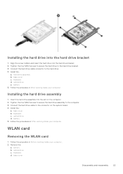
...the four M2L3 screws to secure the hard drive assembly to the hard drive bracket. 3. WLAN card Removing the WLAN card 1. keyboard d. Follow the procedure in After working inside your computer. Insert the hard drive assembly into the slot on the system board. 4....3. Connect the hard drive cable to the hard drive. 4. Install the: a. Remove the: a. keyboard c. base cover Disassembly and reassembly 23 hard drive assembly b. optical drive e. base cover b. keyboard d. Install the: a. base cover c. Follow the procedure in Before working inside your computer Installing the...
...the four M2L3 screws to secure the hard drive assembly to the hard drive bracket. 3. WLAN card Removing the WLAN card 1. keyboard d. Follow the procedure in After working inside your computer. Insert the hard drive assembly into the slot on the system board. 4....3. Connect the hard drive cable to the hard drive. 4. Install the: a. Remove the: a. keyboard c. base cover Disassembly and reassembly 23 hard drive assembly b. optical drive e. base cover b. keyboard d. Install the: a. base cover c. Follow the procedure in Before working inside your computer Installing the...
Vostro 15-3568 Owners Manual
Page 24
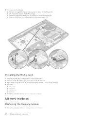
... the WLAN card. 3. d. base cover b. battery 5. Place the securing tab on the WLAN card and tighten the M2L3 screw on the system board [4]. optical drive d. keyboard c. 3. Lift the tab that secures the tab to the connector on the system board. 2. Disconnect the WLAN cables from the connector on the computer. 4. Connect...
... the WLAN card. 3. d. base cover b. battery 5. Place the securing tab on the WLAN card and tighten the M2L3 screw on the system board [4]. optical drive d. keyboard c. 3. Lift the tab that secures the tab to the connector on the system board. 2. Disconnect the WLAN cables from the connector on the computer. 4. Connect...
Vostro 15-3568 Owners Manual
Page 25
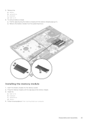
battery b. optical drive c. To remove memory module: a. Pull the clips securing the memory module until the clips secure the memory module. 3. b. base cover b. base cover 3. battery 4. Install the: a. keyboard c. Disassembly and reassembly 25 Remove the: a. Installing the memory module 1. optical drive d. Press the memory module until the memory module pops up [1]. keyboard d. Insert the memory module into the memory socket. 2. 2. Follow the procedures in After working inside your computer. Remove the memory module from the system board [2].
battery b. optical drive c. To remove memory module: a. Pull the clips securing the memory module until the clips secure the memory module. 3. b. base cover b. base cover 3. battery 4. Install the: a. keyboard c. Disassembly and reassembly 25 Remove the: a. Installing the memory module 1. optical drive d. Press the memory module until the memory module pops up [1]. keyboard d. Insert the memory module into the memory socket. 2. 2. Follow the procedures in After working inside your computer. Remove the memory module from the system board [2].
Vostro 15-3568 Owners Manual
Page 26
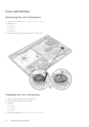
Follow the procedure in After working inside your computer. 2. keyboard d. battery 4. optical drive c. base cover 3. battery b. Press the battery until it clicks into the battery slot. 2. optical drive d. Insert the coin cell battery into place. 3. Install the: a. Installing the coin cell battery 1. Coin-cell battery Removing the coin cell battery 1. Remove the: a. Use a plastic scribe to lift the battery out of the slot [1,2]. battery b. keyboard c. Follow the procedures in Before working inside your computer. 26 Disassembly and reassembly
Follow the procedure in After working inside your computer. 2. keyboard d. battery 4. optical drive c. base cover 3. battery b. Press the battery until it clicks into the battery slot. 2. optical drive d. Insert the coin cell battery into place. 3. Install the: a. Installing the coin cell battery 1. Coin-cell battery Removing the coin cell battery 1. Remove the: a. Use a plastic scribe to lift the battery out of the slot [1,2]. battery b. keyboard c. Follow the procedures in Before working inside your computer. 26 Disassembly and reassembly
Vostro 15-3568 Owners Manual
Page 27
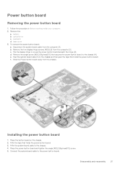
.... Peel the system board cable from the computer [2]. Slide the Power button board away from the computer [1]. Place the button board on the chassis. 2. battery b. keyboard d. Disassembly and reassembly 27 Remove the: a. c. Installing the power button board 1. Place the power button board and tighten the single [M2L2(Big head07)] screw. 5. Power...
.... Peel the system board cable from the computer [2]. Slide the Power button board away from the computer [1]. Place the button board on the chassis. 2. battery b. keyboard d. Disassembly and reassembly 27 Remove the: a. c. Installing the power button board 1. Place the power button board and tighten the single [M2L2(Big head07)] screw. 5. Power...
Vostro 15-3568 Owners Manual
Page 28
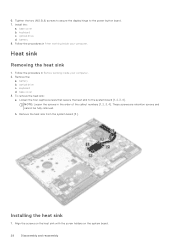
... screws and cannot be fully removed. Align the screws on the heat sink with the screw holders on the system board. 28 Disassembly and reassembly keyboard c. To remove the heat sink: a. b. 6. keyboard d. Heat sink Removing the heat sink 1. Installing the heat sink 1. Install the: a.
... screws and cannot be fully removed. Align the screws on the heat sink with the screw holders on the system board. 28 Disassembly and reassembly keyboard c. To remove the heat sink: a. b. 6. keyboard d. Heat sink Removing the heat sink 1. Installing the heat sink 1. Install the: a.
Vostro 15-3568 Owners Manual
Page 29
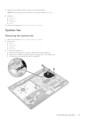
... the two M2L5 screws that secure the system fan to the system board. Follow the procedure in the order of the callout numbers [1, 2, 3, 4]. 3. Remove the: a. keyboard c. battery 4. optical drive c. Lift and remove the system fan from the system board [1]. optical drive d. To remove the system fan: a. 2. Tighten the four captive screws...
... the two M2L5 screws that secure the system fan to the system board. Follow the procedure in the order of the callout numbers [1, 2, 3, 4]. 3. Remove the: a. keyboard c. battery 4. optical drive c. Lift and remove the system fan from the system board [1]. optical drive d. To remove the system fan: a. 2. Tighten the four captive screws...
Vostro 15-3568 Owners Manual
Page 30
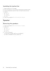
... from the computer [2]. 30 Disassembly and reassembly battery 5. To remove the speakers: a. optical drive d. Remove the: a. Follow the procedure in After working inside your computer. 2. keyboard d. Align the system fan on the chassis. 2. Secure the system fan to the system board connector. 4. Install the: a. base cover...
... from the computer [2]. 30 Disassembly and reassembly battery 5. To remove the speakers: a. optical drive d. Remove the: a. Follow the procedure in After working inside your computer. 2. keyboard d. Align the system fan on the chassis. 2. Secure the system fan to the system board connector. 4. Install the: a. base cover...
Vostro 15-3568 Owners Manual
Page 31
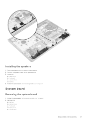
keyboard c. Follow the procedure in Before working inside your computer System board Removing the system board 1. base cover e. Follow the procedure in After working inside your computer. 2. battery 4. battery b. Place the speakers into the slots on the computer. 2. Connect the speaker cable to the system board. 3. keyboard d. Install the: a. optical drive d. Installing the speakers 1. optical drive c. base cover b. Remove the: a. WLAN card Disassembly and reassembly 31
keyboard c. Follow the procedure in Before working inside your computer System board Removing the system board 1. base cover e. Follow the procedure in After working inside your computer. 2. battery 4. battery b. Place the speakers into the slots on the computer. 2. Connect the speaker cable to the system board. 3. keyboard d. Install the: a. optical drive d. Installing the speakers 1. optical drive c. base cover b. Remove the: a. WLAN card Disassembly and reassembly 31
Vostro 15-3568 Owners Manual
Page 35
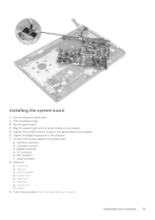
.... touchpad connector c. eDP connector f. Follow the procedure in After working inside your computer. Connect the following cables to the computer. 7. I/O connector e. memory module d. optical drive h. keyboard g. a. power connector 8. Flip the system board. 4. Tighten the two M2L3 screws to secure the system board to the computer. 6. heat sink c. speaker connector d. WLAN Card...
.... touchpad connector c. eDP connector f. Follow the procedure in After working inside your computer. Connect the following cables to the computer. 7. I/O connector e. memory module d. optical drive h. keyboard g. a. power connector 8. Flip the system board. 4. Tighten the two M2L3 screws to secure the system board to the computer. 6. heat sink c. speaker connector d. WLAN Card...
Vostro 15-3568 Owners Manual
Page 36
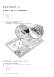
... the: a. Install the: a. Follow the procedure in Before working inside your computer. 2. Installing the Input-Output board 1. Input-Output board Removing the Input-Output board 1. keyboard 36 Disassembly and reassembly base cover e. Connect the input/output (I /O board cable [1]. optical drive c. b. hard drive assembly b. battery b. Place the I /O board from the computer [2, 3]. Remove...
... the: a. Install the: a. Follow the procedure in Before working inside your computer. 2. Installing the Input-Output board 1. Input-Output board Removing the Input-Output board 1. keyboard 36 Disassembly and reassembly base cover e. Connect the input/output (I /O board cable [1]. optical drive c. b. hard drive assembly b. battery b. Place the I /O board from the computer [2, 3]. Remove...


