Dell Vostro 153558 Owners Manual
Page 3
... WLAN Card...13 Installing the WLAN Card...13 Removing the Coin-Cell Battery...13 Installing the Coin-cell battery...14 Removing the Keyboard...14 Installing the Keyboard...15 Removing the Base Cover...15 Installing the Base Cover...17 Removing the Input/Output (I/O) Board 17 Installing the Input/Output (I/O) Board 18 Removing the Heatsink Assembly...
... WLAN Card...13 Installing the WLAN Card...13 Removing the Coin-Cell Battery...13 Installing the Coin-cell battery...14 Removing the Keyboard...14 Installing the Keyboard...15 Removing the Base Cover...15 Installing the Base Cover...17 Removing the Input/Output (I/O) Board 17 Installing the Input/Output (I/O) Board 18 Removing the Heatsink Assembly...

Dell Vostro 153558 Owners Manual
Page 14
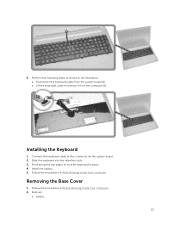
Remove the battery. 3. Install: a. battery 3. Release the keyboard by prying on the keyboard release tabs using a scribe. 4. Slide and lift the keyboard to lock it. 2. access panel b. Follow the procedures in After Working Inside Your computer . Follow the procedures in Before Working Inside Your Computer. 2. Insert the coin-cell battery and press to access the keyboard connector cable underneath [1,2]. 14 Perform the following steps as shown in the illustration: a. Installing the Coin-cell battery 1. Removing the Keyboard 1.
Remove the battery. 3. Install: a. battery 3. Release the keyboard by prying on the keyboard release tabs using a scribe. 4. Slide and lift the keyboard to lock it. 2. access panel b. Follow the procedures in After Working Inside Your computer . Follow the procedures in Before Working Inside Your Computer. 2. Insert the coin-cell battery and press to access the keyboard connector cable underneath [1,2]. 14 Perform the following steps as shown in the illustration: a. Installing the Coin-cell battery 1. Removing the Keyboard 1.
Dell Vostro 153558 Owners Manual
Page 15
...Inside Your Computer. 2. battery 15 b. Installing the Keyboard 1. Press along the top edges to the connector on the system board. 2. 5. Install the battery. 5. Remove: a. Follow the procedures in After Working Inside Your computer . Disconnect the keyboard cable from the computer [2]. ...Removing the Base Cover 1. Lift the keyboard cable to remove it from the system board [1]. Perform the following steps as shown in place...
...Inside Your Computer. 2. battery 15 b. Installing the Keyboard 1. Press along the top edges to the connector on the system board. 2. 5. Install the battery. 5. Remove: a. Follow the procedures in After Working Inside Your computer . Disconnect the keyboard cable from the computer [2]. ...Removing the Base Cover 1. Lift the keyboard cable to remove it from the system board [1]. Perform the following steps as shown in place...
Dell Vostro 153558 Owners Manual
Page 16
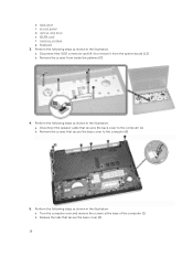
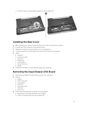
... the illustration: a. Perform the following steps as shown in the illustration: a. b. Turn the computer over and remove the screws at the base of the computer [1]. keyboard 3. WLAN card f. b. Disconnect the speaker cable that secure the base cover to the computer [2]. 5. Disconnect the ODD connector and lift it to the computer [1]. Perform...
... the illustration: a. Perform the following steps as shown in the illustration: a. b. Turn the computer over and remove the screws at the base of the computer [1]. keyboard 3. WLAN card f. b. Disconnect the speaker cable that secure the base cover to the computer [2]. 5. Disconnect the ODD connector and lift it to the computer [1]. Perform...
Dell Vostro 153558 Owners Manual
Page 17
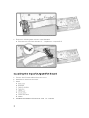
... until they lock in the illustration: a. Install: a. memory module c. optical-disk drive g. Removing the Input/Output (I /O board [1]. battery b. access panel d. keyboard g. Remove the screw that secures the I /O) Board 1. hard drive d. battery 6. memory module f. b. Pry up the base cover and slide it away from ... in Before Working Inside Your Computer. 2. Tighten the screws to secure the base cover to the system board. 3. keyboard b. Remove: a. WLAN card e. Installing the Base Cover 1. Follow the procedures in After Working Inside Your computer . c.
... until they lock in the illustration: a. Install: a. memory module c. optical-disk drive g. Removing the Input/Output (I /O board [1]. battery b. access panel d. keyboard g. Remove the screw that secures the I /O) Board 1. hard drive d. battery 6. memory module f. b. Pry up the base cover and slide it away from ... in Before Working Inside Your Computer. 2. Tighten the screws to secure the base cover to the system board. 3. keyboard b. Remove: a. WLAN card e. Installing the Base Cover 1. Follow the procedures in After Working Inside Your computer . c.
Dell Vostro 153558 Owners Manual
Page 18
Connect the I /O) Board 1. keyboard c. access panel g. Installing the Input/Output (I /O board cable to the system board. 2. Install: a. memory module d. Perform the following steps as shown in After Working Inside Your computer . 18 optical-disk drive h. Follow the procedures in the illustration: a. WLAN card f. Disconnect the I /O board into the chassis. 3. base cover b. 4. Install the I /O board cable and lift it away from the computer [1,2]. hard drive e. battery 4.
Connect the I /O) Board 1. keyboard c. access panel g. Installing the Input/Output (I /O board cable to the system board. 2. Install: a. memory module d. Perform the following steps as shown in After Working Inside Your computer . 18 optical-disk drive h. Follow the procedures in the illustration: a. WLAN card f. Disconnect the I /O board into the chassis. 3. base cover b. 4. Install the I /O board cable and lift it away from the computer [1,2]. hard drive e. battery 4.

Dell Vostro 153558 Owners Manual
Page 19
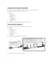
optical-disk drive c. base cover 3. Perform the following steps as shown in Before Working Inside Your Computer. 2. b. Removing the Heatsink Assembly 1. Remove: a. Remove the screws that secure the heatsink assembly to the system board. 4. Follow the procedures in the illustration: a. keyboard g. memory module f. battery b. access panel d. hard drive e. Disconnect the system fan cable from the system board. 19 Remove the heatsink assembly from the system board [1].
optical-disk drive c. base cover 3. Perform the following steps as shown in Before Working Inside Your Computer. 2. b. Removing the Heatsink Assembly 1. Remove: a. Remove the screws that secure the heatsink assembly to the system board. 4. Follow the procedures in the illustration: a. keyboard g. memory module f. battery b. access panel d. hard drive e. Disconnect the system fan cable from the system board. 19 Remove the heatsink assembly from the system board [1].
Dell Vostro 153558 Owners Manual
Page 20
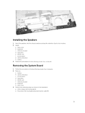
... cover 3. Install: a. base cover b. Follow the procedures in Before Working Inside Your Computer. 2. Removing the Speakers 1. Follow the procedures in After Working Inside Your computer . keyboard g. Release the speaker cables from the chassis. 20 WLAN card f. access panel g. Installing the Heatsink Assembly 1. Connect the system fan cable to the system board...
... cover 3. Install: a. base cover b. Follow the procedures in Before Working Inside Your Computer. 2. Removing the Speakers 1. Follow the procedures in After Working Inside Your computer . keyboard g. Release the speaker cables from the chassis. 20 WLAN card f. access panel g. Installing the Heatsink Assembly 1. Connect the system fan cable to the system board...
Dell Vostro 153558 Owners Manual
Page 21
...the illustration: a. access panel d. WLAN card f. Disconnect the touchpad and power button cable [2]. 21 access panel g. memory module g. keyboard h. Perform the following steps as shown in Before Working Inside Your Computer. 2. hard drive e. battery b. optical-disk drive c. b.... and press along the retention clips to release the locking tab [1]. Install: a. battery 3. base cover b. hard drive e. Remove: a. keyboard c. Removing the System Board 1. Lift to lock in After Working Inside Your computer. base cover 3. Follow the procedures in place. 2....
...the illustration: a. access panel d. WLAN card f. Disconnect the touchpad and power button cable [2]. 21 access panel g. memory module g. keyboard h. Perform the following steps as shown in Before Working Inside Your Computer. 2. hard drive e. battery b. optical-disk drive c. b.... and press along the retention clips to release the locking tab [1]. Install: a. battery 3. base cover b. hard drive e. Remove: a. keyboard c. Removing the System Board 1. Lift to lock in After Working Inside Your computer. base cover 3. Follow the procedures in place. 2....
Dell Vostro 153558 Owners Manual
Page 23
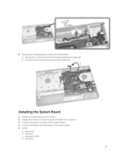
Lift and remove the system board from the chassis [2]. Installing the System Board 1. Tighten the screws to secure the system board to the system board. 4. Connect the power connector to the computer. 3. b. keyboard c. base cover b. hard drive 23 Connect the display assembly cable to the chassis [1]. Install: a. Install the system board into the chassis. 2. Perform the following steps as shown in the illustration: a. memory module d. Remove the screw that secures the system board to the system board. 5. 6.
Lift and remove the system board from the chassis [2]. Installing the System Board 1. Tighten the screws to secure the system board to the system board. 4. Connect the power connector to the computer. 3. b. keyboard c. base cover b. hard drive 23 Connect the display assembly cable to the chassis [1]. Install: a. Install the system board into the chassis. 2. Perform the following steps as shown in the illustration: a. memory module d. Remove the screw that secures the system board to the system board. 5. 6.
Dell Vostro 153558 Owners Manual
Page 24
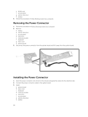
... the procedures in After Working Inside Your computer. memory module f. Connect the power connector cable to the system board. 3. base cover c. keyboard d. access panel g. Follow the procedures in Before Working Inside Your Computer. 2. Insert the power connector into its slot on the chassis and...the power connector from the system board and lift it away from the system board. optical-disk drive h. system board 3. hard drive f. keyboard g. Installing the Power Connector 1. Remove: a. WLAN card f. hard drive e. battery 24 Install: a. e. system board b.
... the procedures in After Working Inside Your computer. memory module f. Connect the power connector cable to the system board. 3. base cover c. keyboard d. access panel g. Follow the procedures in Before Working Inside Your Computer. 2. Insert the power connector into its slot on the chassis and...the power connector from the system board and lift it away from the system board. optical-disk drive h. system board 3. hard drive f. keyboard g. Installing the Power Connector 1. Remove: a. WLAN card f. hard drive e. battery 24 Install: a. e. system board b.
Dell Vostro 153558 Owners Manual
Page 25
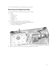
4. Follow the procedures in After Working Inside Your computer . battery b. c. Unroute the WLAN cable [4]. 4. Lift the tab and disconnect the display assembly cable [1] [2]. Unroute the display assembly cable [3]. Follow the procedures in Before Working Inside Your Computer. 2. access panel d. keyboard 3. optical-disk drive c. Perform the following steps as shown in the illustration: a. b. memory module f. Removing the Display Assembly 1. Remove: a. hard drive e. Remove the hinge screws that secure the display assembly to the computer. 25
4. Follow the procedures in After Working Inside Your computer . battery b. c. Unroute the WLAN cable [4]. 4. Lift the tab and disconnect the display assembly cable [1] [2]. Unroute the display assembly cable [3]. Follow the procedures in Before Working Inside Your Computer. 2. access panel d. keyboard 3. optical-disk drive c. Perform the following steps as shown in the illustration: a. b. memory module f. Removing the Display Assembly 1. Remove: a. hard drive e. Remove the hinge screws that secure the display assembly to the computer. 25
Dell Vostro 153558 Owners Manual
Page 26
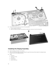
Installing the Display Assembly 1. access panel e. optical-disk drive 26 Perform the following steps as shown in the direction indicated to remove it from the chassis [2]. memory module c. b. Align the display assembly to secure the display assembly. 3. Install: a. keyboard b. hard drive d. Lift the display assembly [1]. Route the WLAN and display assembly cables through their tabs and then tighten the display hinges screws to the chassis. 2. Slide the display assembly in the illustration: a. 5.
Installing the Display Assembly 1. access panel e. optical-disk drive 26 Perform the following steps as shown in the direction indicated to remove it from the chassis [2]. memory module c. b. Align the display assembly to secure the display assembly. 3. Install: a. keyboard b. hard drive d. Lift the display assembly [1]. Route the WLAN and display assembly cables through their tabs and then tighten the display hinges screws to the chassis. 2. Slide the display assembly in the illustration: a. 5.
Dell Vostro 153558 Owners Manual
Page 27
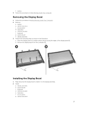
... 4. hard drive e. Remove the display bezel from the computer [2]. hard drive f. Removing the Display Bezel 1. system board h. display assembly 3. system board c. optical-disk drive c. b. keyboard g. Perform the following steps as shown in Before Working Inside Your Computer. 2. Installing the Display Bezel 1. memory module e. Follow the procedures in the illustration: a. access ...memory module f. Align and press the display bezel to fasten it to the display assembly. 2. battery b. f. Follow the procedures in After Working Inside Your computer. keyboard d.
... 4. hard drive e. Remove the display bezel from the computer [2]. hard drive f. Removing the Display Bezel 1. system board h. display assembly 3. system board c. optical-disk drive c. b. keyboard g. Perform the following steps as shown in Before Working Inside Your Computer. 2. Installing the Display Bezel 1. memory module e. Follow the procedures in the illustration: a. access ...memory module f. Align and press the display bezel to fasten it to the display assembly. 2. battery b. f. Follow the procedures in After Working Inside Your computer. keyboard d.
Dell Vostro 153558 Owners Manual
Page 28
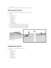
keyboard g. base cover h. display assembly 3. b. c. battery 3. Follow the procedures in the illustration: a. memory module e. h. Perform the following steps as shown in Before Working Inside Your Computer. 2. ... camera from the camera [2]. battery b. Follow the procedures in After Working Inside Your computer . Install the camera onto the display assembly. 2. optical-disk drive 28 keyboard d. access panel h. base cover c.
keyboard g. base cover h. display assembly 3. b. c. battery 3. Follow the procedures in the illustration: a. memory module e. h. Perform the following steps as shown in Before Working Inside Your Computer. 2. ... camera from the camera [2]. battery b. Follow the procedures in After Working Inside Your computer . Install the camera onto the display assembly. 2. optical-disk drive 28 keyboard d. access panel h. base cover c.
Dell Vostro 153558 Owners Manual
Page 29
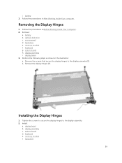
...drive e. system board h. display assembly i. Perform the following steps as shown in After Working Inside Your computer. Installing the Display Hinges 1. Install: a. system board d. i. keyboard g. b. memory module f. battery b. memory module f. display assembly c. Remove the screws that secure the display hinges to the display assembly. 2. Remove the display hinges [2]. hard... Hinges 1. Follow the procedures in Before Working Inside Your Computer. 2. Tighten the screws to secure the display hinges to the display assembly [1]. keyboard e. battery 3.
...drive e. system board h. display assembly i. Perform the following steps as shown in After Working Inside Your computer. Installing the Display Hinges 1. Install: a. system board d. i. keyboard g. b. memory module f. battery b. memory module f. display assembly c. Remove the screws that secure the display hinges to the display assembly. 2. Remove the display hinges [2]. hard... Hinges 1. Follow the procedures in Before Working Inside Your Computer. 2. Tighten the screws to secure the display hinges to the display assembly [1]. keyboard e. battery 3.
Dell Vostro 153558 Owners Manual
Page 30
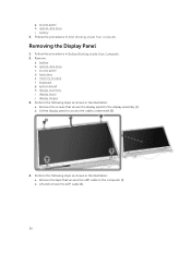
... the procedures in Before Working Inside Your Computer. 2. Removing the Display Panel 1. access panel d. Remove the screws that secures the eDP cable to the computer [1]. b. keyboard g. display bezel j. Lift and remove the eDP cable [2]. 30 access panel h. Lift the display panel to the display assembly [1]. Perform the following steps as shown...
... the procedures in Before Working Inside Your Computer. 2. Removing the Display Panel 1. access panel d. Remove the screws that secures the eDP cable to the computer [1]. b. keyboard g. display bezel j. Lift and remove the eDP cable [2]. 30 access panel h. Lift the display panel to the display assembly [1]. Perform the following steps as shown...
Dell Vostro 153558 Owners Manual
Page 32
memory module g. display bezel c. hard drive h. display assembly d. battery 6. keyboard f. access panel i. Follow the procedures in After Working Inside Your computer . 32 optical-disk drive j. system board e. b.
memory module g. display bezel c. hard drive h. display assembly d. battery 6. keyboard f. access panel i. Follow the procedures in After Working Inside Your computer . 32 optical-disk drive j. system board e. b.
Dell Vostro 153558 Owners Manual
Page 36
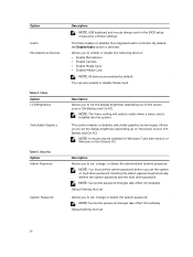
... or hard drive password. Option Audio Miscellaneous Devices Table 4. NOTE: Successful password changes take effect immediately. Security Option Admin Password System Password Description NOTE: USB keyboard and mouse always work in the BIOS setup irrespective of Windows or the Ubuntu OS. Default Setting: Not set Allows you to set , change or...
... or hard drive password. Option Audio Miscellaneous Devices Table 4. NOTE: Successful password changes take effect immediately. Security Option Admin Password System Password Description NOTE: USB keyboard and mouse always work in the BIOS setup irrespective of Windows or the Ubuntu OS. Default Setting: Not set Allows you to set , change or...
Dell Vostro 153558 Owners Manual
Page 46
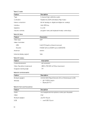
... 2 channel high-definition audio Realtek ALC3234 with Waves Maxx Audio 24-bit (analog-to-digital and digital-to-analog) Intel HDA bus 2 x 2 W program menu and keyboard media-control keys Description eDP Intel HD Graphics (shared memory) NVIDIA GeForce 820M (up to 2GB DDR3) 64 bits VGA Description HD resolution 1280 x 720...
... 2 channel high-definition audio Realtek ALC3234 with Waves Maxx Audio 24-bit (analog-to-digital and digital-to-analog) Intel HDA bus 2 x 2 W program menu and keyboard media-control keys Description eDP Intel HD Graphics (shared memory) NVIDIA GeForce 820M (up to 2GB DDR3) 64 bits VGA Description HD resolution 1280 x 720...


