
Owners Manual
Page 2
... Wireless Ethernet Compatibility Alliance, Inc. Microsoft®, Windows®, MS-DOS®, Windows Vista®, the Windows Vista start button, and Office Outlook® are not followed. WARNING: A WARNING indicates a potential for use of Dell Inc. Trademarks used in the United States and/or other countries. The Bluetooth® word mark is a registered trademark of Microsoft Corporation in this publication to refer to hardware...
... Wireless Ethernet Compatibility Alliance, Inc. Microsoft®, Windows®, MS-DOS®, Windows Vista®, the Windows Vista start button, and Office Outlook® are not followed. WARNING: A WARNING indicates a potential for use of Dell Inc. Trademarks used in the United States and/or other countries. The Bluetooth® word mark is a registered trademark of Microsoft Corporation in this publication to refer to hardware...

Owners Manual
Page 3
......8 Turning Off Your Computer 9 After Working Inside Your Computer 9 2 Removing The Battery 11 Installing The Battery...11 3 Removing The Secure Digital (SD) Card 13 Installing The Secure Digital (SD) Card 13 4 Removing The Hinge Cover 15 Installing The Hinge Cover 16 5 Removing The Keyboard 17 Installing The Keyboard 18 6 Removing The Optical Drive 19 Installing The Optical Drive 20 7 Removing The Memory Module 21 Installing The Memory Module 22 8 Removing The Palm Rest 23 Installing The Palm Rest 25 Downloaded from...
......8 Turning Off Your Computer 9 After Working Inside Your Computer 9 2 Removing The Battery 11 Installing The Battery...11 3 Removing The Secure Digital (SD) Card 13 Installing The Secure Digital (SD) Card 13 4 Removing The Hinge Cover 15 Installing The Hinge Cover 16 5 Removing The Keyboard 17 Installing The Keyboard 18 6 Removing The Optical Drive 19 Installing The Optical Drive 20 7 Removing The Memory Module 21 Installing The Memory Module 22 8 Removing The Palm Rest 23 Installing The Palm Rest 25 Downloaded from...

Owners Manual
Page 4
9 Removing The Power Button Board 27 Installing The Power Button Board 28 10 Removing The Hard Drive 29 Installing The Hard Drive 30 11 Removing The Wireless Local Area Network (WLAN) Card...........31 Installing The Wireless Local Area Network (WLAN) Card 32 12 Removing The Coin-Cell Battery 33 Installing The Coin-Cell Battery 34 13 Removing The Audio Board 35 Installing The Audio Board 37 14 Removing The USB Board 39 Installing The USB Board 40 15 Removing The CPU Fan Assembly And The Heatsink 41 Installing The CPU Fan Assembly And The Heatsink...
9 Removing The Power Button Board 27 Installing The Power Button Board 28 10 Removing The Hard Drive 29 Installing The Hard Drive 30 11 Removing The Wireless Local Area Network (WLAN) Card...........31 Installing The Wireless Local Area Network (WLAN) Card 32 12 Removing The Coin-Cell Battery 33 Installing The Coin-Cell Battery 34 13 Removing The Audio Board 35 Installing The Audio Board 37 14 Removing The USB Board 39 Installing The USB Board 40 15 Removing The CPU Fan Assembly And The Heatsink 41 Installing The CPU Fan Assembly And The Heatsink...
Owners Manual
Page 5
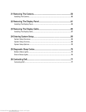
21 Removing The Camera 59 Installing The Camera...60 22 Removing The Display Panel 61 Installing The Display Panel 64 23 Removing The Display Cable 65 Installing The Display Cable 67 24 Entering System Setup 69 System Setup Overview 69 System Setup Screens...69 System Setup Options...70 25 Diagnostic Beep Codes 75 Battery Status Lights...76 Device Status Lights...76 26 Contacting Dell 77 Contacting Dell...77 Downloaded from www.Manualslib.com manuals search engine
21 Removing The Camera 59 Installing The Camera...60 22 Removing The Display Panel 61 Installing The Display Panel 64 23 Removing The Display Cable 65 Installing The Display Cable 67 24 Entering System Setup 69 System Setup Overview 69 System Setup Screens...69 System Setup Options...70 25 Diagnostic Beep Codes 75 Battery Status Lights...76 Device Status Lights...76 26 Contacting Dell 77 Contacting Dell...77 Downloaded from www.Manualslib.com manuals search engine
Owners Manual
Page 7
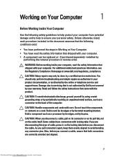
... or telephone service and support team. CAUTION: Handle components and cards with your computer. • A component can be done by performing the removal procedure in this type of the computer. CAUTION: Many repairs may only be replaced or--if purchased separately--installed by a certified service technician. Unless otherwise noted, each procedure included in reverse order. Damage due to servicing that the...
... or telephone service and support team. CAUTION: Handle components and cards with your computer. • A component can be done by performing the removal procedure in this type of the computer. CAUTION: Many repairs may only be replaced or--if purchased separately--installed by a certified service technician. Unless otherwise noted, each procedure included in reverse order. Damage due to servicing that the...

Owners Manual
Page 8
... a network cable, first unplug the cable from the network device. 4. While you work, periodically touch an unpainted metal surface to ground the system board. Remove any installed ExpressCards or Smart Cards from www.Manualslib.com manuals search engine Recommended Tools The procedures in this document may require the following steps before you service the computer. 7. Disconnect your computer and all network cables from being scratched. 2. Open...
... a network cable, first unplug the cable from the network device. 4. While you work, periodically touch an unpainted metal surface to ground the system board. Remove any installed ExpressCards or Smart Cards from www.Manualslib.com manuals search engine Recommended Tools The procedures in this document may require the following steps before you service the computer. 7. Disconnect your computer and all network cables from being scratched. 2. Open...

Owners Manual
Page 9
... scribe • Flash BIOS update program CD Turning Off Your Computer CAUTION: To avoid losing data, save and close all open programs before turning on your computer. 1. Connect any external devices, such as a port replicator, battery slice, or media base, and replace any external devices, cards, and cables before you connect any cards, such as shown below, and then click Shut Down. • In Windows XP: Click Start → Turn Off Computer...
... scribe • Flash BIOS update program CD Turning Off Your Computer CAUTION: To avoid losing data, save and close all open programs before turning on your computer. 1. Connect any external devices, such as a port replicator, battery slice, or media base, and replace any external devices, cards, and cables before you connect any cards, such as shown below, and then click Shut Down. • In Windows XP: Click Start → Turn Off Computer...

Owners Manual
Page 21
Remove the keyboard. 4. Remove the memory module from the computer. 21 Downloaded from the memory module until it pops up. 5. Removing The Memory Module 7 1. Pry the retention clips away from www.Manualslib.com manuals search engine Remove the battery. 3. Follow the procedures in Before Working On Your Computer. 2.
Remove the keyboard. 4. Remove the memory module from the computer. 21 Downloaded from the memory module until it pops up. 5. Removing The Memory Module 7 1. Pry the retention clips away from www.Manualslib.com manuals search engine Remove the battery. 3. Follow the procedures in Before Working On Your Computer. 2.

Owners Manual
Page 25
... Rest 1. Align and adjust the palm rest into position before pressing it down to their respective connectors. 4. Connect the power board cable and touchpad cable to secure all the snaps. 3. Follow the procedures in After Working Inside Your Computer. 25 Downloaded from www.Manualslib.com manuals search engine Install the battery. 8. Insert the palm rest towards the display screen at a 30-degree angle. 2. Install the keyboard. 7.
... Rest 1. Align and adjust the palm rest into position before pressing it down to their respective connectors. 4. Connect the power board cable and touchpad cable to secure all the snaps. 3. Follow the procedures in After Working Inside Your Computer. 25 Downloaded from www.Manualslib.com manuals search engine Install the battery. 8. Insert the palm rest towards the display screen at a 30-degree angle. 2. Install the keyboard. 7.

Owners Manual
Page 44
Tighten the cam-screw in After Working Inside Your Computer. 44 Downloaded from www.Manualslib.com manuals search engine Follow the procedures in a clockwise direction to the locked position. 3. Installing The Processor 1. Install the CPU fan assembly and the heatsink. 4. Install the battery. 7. Insert the processor into the processor socket. Ensure the processor is properly seated. 2. Install the palm rest. 5. Install the keyboard. 6.
Tighten the cam-screw in After Working Inside Your Computer. 44 Downloaded from www.Manualslib.com manuals search engine Follow the procedures in a clockwise direction to the locked position. 3. Installing The Processor 1. Install the CPU fan assembly and the heatsink. 4. Install the battery. 7. Insert the processor into the processor socket. Ensure the processor is properly seated. 2. Install the palm rest. 5. Install the keyboard. 6.
Owners Manual
Page 45
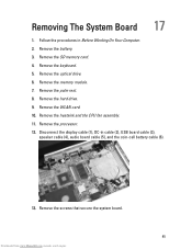
... the display cable (1), DC-in Before Working On Your Computer. 2. Remove the keyboard. 5. Remove the optical drive. 6. Remove the hard drive. 9. Remove the memory module. 7. Remove the processor. 12. Remove the WLAN card. 10. Remove the screws that secure the system board. 45 Downloaded from www.Manualslib.com manuals search engine Follow the procedures in cable (2), USB board cable (3), speaker cable (4), audio board cable (5), and the coin-cell battery cable (6). 13. Remove the SD memory card. 4. Removing The System Board 17 1. Remove the heatsink and the CPU fan...
... the display cable (1), DC-in Before Working On Your Computer. 2. Remove the keyboard. 5. Remove the optical drive. 6. Remove the hard drive. 9. Remove the memory module. 7. Remove the processor. 12. Remove the WLAN card. 10. Remove the screws that secure the system board. 45 Downloaded from www.Manualslib.com manuals search engine Follow the procedures in cable (2), USB board cable (3), speaker cable (4), audio board cable (5), and the coin-cell battery cable (6). 13. Remove the SD memory card. 4. Removing The System Board 17 1. Remove the heatsink and the CPU fan...

Owners Manual
Page 47
... Downloaded from www.Manualslib.com manuals search engine Install the hard drive. 8. Install the SD memory card. 13. Install the heatsink and the CPU fan assembly. 6. Follow the procedures in place. 3. Connect the LCD cable, DC-in place. 2. Install the battery. 14. Insert the system board with the LAN, VGA, HDMI, and USB connectors into their respective sockets and align the system board in cable, USB board cable, audio board cable, coin-cell battery cable, and the speaker cable. 4. Install the memory module. 10. Install...
... Downloaded from www.Manualslib.com manuals search engine Install the hard drive. 8. Install the SD memory card. 13. Install the heatsink and the CPU fan assembly. 6. Follow the procedures in place. 3. Connect the LCD cable, DC-in place. 2. Install the battery. 14. Insert the system board with the LAN, VGA, HDMI, and USB connectors into their respective sockets and align the system board in cable, USB board cable, audio board cable, coin-cell battery cable, and the speaker cable. 4. Install the memory module. 10. Install...
Owners Manual
Page 49
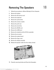
Remove the keyboard. 5. Remove the processor. 13. Remove the hinge cover. 15. Release the speaker cable from www.Manualslib.com manuals search engine Remove the battery. 3. Remove the memory module. 7. Remove the WLAN card. 10. Remove the heatsink and the CPU fan assembly. 12. Remove the SD memory card. 4. Remove the USB board. 11. Remove the palm rest. 8. Remove the system board. 14. Removing The Speakers 1. Remove the display assembly. 16. Remove the hard drive. 9. Press the securing latches and lift up the...
Remove the keyboard. 5. Remove the processor. 13. Remove the hinge cover. 15. Release the speaker cable from www.Manualslib.com manuals search engine Remove the battery. 3. Remove the memory module. 7. Remove the WLAN card. 10. Remove the heatsink and the CPU fan assembly. 12. Remove the SD memory card. 4. Remove the USB board. 11. Remove the palm rest. 8. Remove the system board. 14. Removing The Speakers 1. Remove the display assembly. 16. Remove the hard drive. 9. Press the securing latches and lift up the...
Owners Manual
Page 51
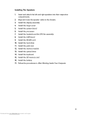
... CPU fan assembly. 8. Install the WLAN card. 10. Install the memory module. 13. Install the optical drive. 14. Follow the procedures in After Working Inside Your Computer. 51 Downloaded from www.Manualslib.com manuals search engine Install the display assembly. 4. Install the hard drive. 11. Install the battery. 17. Install the keyboard. 15. Install the USB board. 9. Install the hinge cover. 5. Install the SD memory card. 16. Align and route the speaker cable to the chassis. 3. Install the system board. 6. Install the processor. 7. Install...
... CPU fan assembly. 8. Install the WLAN card. 10. Install the memory module. 13. Install the optical drive. 14. Follow the procedures in After Working Inside Your Computer. 51 Downloaded from www.Manualslib.com manuals search engine Install the display assembly. 4. Install the hard drive. 11. Install the battery. 17. Install the keyboard. 15. Install the USB board. 9. Install the hinge cover. 5. Install the SD memory card. 16. Align and route the speaker cable to the chassis. 3. Install the system board. 6. Install the processor. 7. Install...

Owners Manual
Page 64
.... Install the battery. 14. Insert and route the display cable and wireless antennae to the left and right brackets to the top cover. 4. Align the WLAN antennae routing cable to its brackets to the display panel and secure the screws. 2. Install the keyboard. 12. Align the display panel with its holder and connect the antennae to the camera module. 7. Connect the camera cable to the WLAN card. 5. Installing The Display Panel 1. Install the optical drive...
.... Install the battery. 14. Insert and route the display cable and wireless antennae to the left and right brackets to the top cover. 4. Align the WLAN antennae routing cable to its brackets to the display panel and secure the screws. 2. Install the keyboard. 12. Align the display panel with its holder and connect the antennae to the camera module. 7. Connect the camera cable to the WLAN card. 5. Installing The Display Panel 1. Install the optical drive...
Owners Manual
Page 69
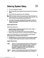
...; change the system configuration information after you add, change, or remove any hardware in your computer. • set the type of the System Setup window. This field provides a menu to access the System Setup options. Once the F2 prompt appears, press immediately. NOTE: The F2 prompt indicates that define the hardware installed on top of hard drive installed. Then, shut down the System Setup screen information for the F2 prompt to work...
...; change the system configuration information after you add, change, or remove any hardware in your computer. • set the type of the System Setup window. This field provides a menu to access the System Setup options. Once the F2 prompt appears, press immediately. NOTE: The F2 prompt indicates that define the hardware installed on top of hard drive installed. Then, shut down the System Setup screen information for the F2 prompt to work...

Owners Manual
Page 70
... computer. Press < Enter> to make changes to the Options List. Use the following keys to navigate through the System Setup screens: Keystroke Action < F2 > Displays information on any selected item in the System Setup. < Esc > Exit from www.Manualslib.com manuals search engine As a Menu option is highlighted, the Options List lists the options that define the hardware installed on the computer's internal calendar. 70 Downloaded from current view or switch the current...
... computer. Press < Enter> to make changes to the Options List. Use the following keys to navigate through the System Setup screens: Keystroke Action < F2 > Displays information on any selected item in the System Setup. < Esc > Exit from www.Manualslib.com manuals search engine As a Menu option is highlighted, the Options List lists the options that define the hardware installed on the computer's internal calendar. 70 Downloaded from current view or switch the current...

Owners Manual
Page 71
... Default: Enabled SpeedStep feature. Displays the BIOS revision. Displays the product name and the model number. Displays the service tag of the optical drive. Displays the speed of the AC adapter. Displays the memory in-built on -board network card. 71 Downloaded from www.Manualslib.com manuals search engine Displays the type of the processor. Enable or disable the power Default: Enabled supply to the on the computer. Displays the type of the hard drive. Enable or disable the Intel Default: Enabled Virtualization feature. Displays...
... Default: Enabled SpeedStep feature. Displays the BIOS revision. Displays the product name and the model number. Displays the service tag of the optical drive. Displays the speed of the AC adapter. Displays the memory in-built on -board network card. 71 Downloaded from www.Manualslib.com manuals search engine Displays the type of the processor. Enable or disable the power Default: Enabled supply to the on the computer. Displays the type of the hard drive. Enable or disable the Intel Default: Enabled Virtualization feature. Displays...

Owners Manual
Page 72
... SATA controller Default: AHCI mode to change or delete the administrator password. Allows you enable or disable various on the computer's internal hard drive (HDD). Default: Enabled These fields let you to an AC power source. This feature is enabled only when the AC adapter is not already set, this field can be charged when connected to set a password on -board devices. Enables or disables adapter Default: Enabled warnings. If the service tag is connected. Specifies the behavior of the function key .
... SATA controller Default: AHCI mode to change or delete the administrator password. Allows you enable or disable various on the computer's internal hard drive (HDD). Default: Enabled These fields let you to an AC power source. This feature is enabled only when the AC adapter is not already set, this field can be charged when connected to set a password on -board devices. Enables or disables adapter Default: Enabled warnings. If the service tag is connected. Specifies the behavior of the function key .

Owners Manual
Page 75
... power button. Code Cause and Troubleshooting Steps 1 BIOS ROM checksum in progress or failure System board failure, covers BIOS corruption or ROM error 2 No RAM detected No memory detected 3 Chipset Error (North and South Bridge Chipset, DMA/IMR/ Timer Error) , Time-Of-Day Clock test failure , Gate A20 failure , Super I/O chip failure , Keyboard controller test failure System board failure 4 RAM Read/Write failure Memory failure 5 Real-time clock power fail CMOS battery failure 6 Video BIOS...
... power button. Code Cause and Troubleshooting Steps 1 BIOS ROM checksum in progress or failure System board failure, covers BIOS corruption or ROM error 2 No RAM detected No memory detected 3 Chipset Error (North and South Bridge Chipset, DMA/IMR/ Timer Error) , Time-Of-Day Clock test failure , Gate A20 failure , Super I/O chip failure , Keyboard controller test failure System board failure 4 RAM Read/Write failure Memory failure 5 Real-time clock power fail CMOS battery failure 6 Video BIOS...


