Owner's Manual
Page 5
... 6 Using a Battery 53 Battery Performance 53 Checking the Battery Charge 54 Dell™ QuickSet Battery Meter 54 Microsoft® Windows® Power Meter 55 Charge Gauge 55 Low-Battery Warning 56 Conserving Battery Power 56 Power Management Modes 56 Configuring Power Management Settings . . . . . 58 Accessing Power Options Properties 58 Charging the Battery 58 Replacing the Battery 59 Storing a Battery 60 7 Using...
... 6 Using a Battery 53 Battery Performance 53 Checking the Battery Charge 54 Dell™ QuickSet Battery Meter 54 Microsoft® Windows® Power Meter 55 Charge Gauge 55 Low-Battery Warning 56 Conserving Battery Power 56 Power Management Modes 56 Configuring Power Management Settings . . . . . 58 Accessing Power Options Properties 58 Charging the Battery 58 Replacing the Battery 59 Storing a Battery 60 7 Using...
Owner's Manual
Page 29
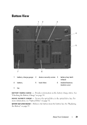
..." on page 59. About Your Computer 29 See "Replacing the Battery" on page 54. For more information, see "Optical Drive" on the battery charge status. Provides information on page 92. D E V I C E S E C U R I T Y S C R E W - Releases the battery from the battery bay. Bottom View 12 3 4 5 7 6 1 battery charge gauge 2 device security screw 3 battery-bay latch release 4 battery 5 hard drive 6 modem/memory module cover 7 fan...
..." on page 59. About Your Computer 29 See "Replacing the Battery" on page 54. For more information, see "Optical Drive" on the battery charge status. Provides information on page 92. D E V I C E S E C U R I T Y S C R E W - Releases the battery from the battery bay. Bottom View 12 3 4 5 7 6 1 battery charge gauge 2 device security screw 3 battery-bay latch release 4 battery 5 hard drive 6 modem/memory module cover 7 fan...
Owner's Manual
Page 54
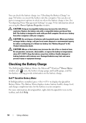
..., press to work with extreme care. Replace the battery only with your computer. Do not use a battery from other computers with a compatible battery purchased from children. Handle damaged or leaking batteries with your local waste disposal or environmental agency for the battery in the Product Information Guide. Dell™ QuickSet Battery Meter If Dell QuickSet is low. CAUTION: Do...
..., press to work with extreme care. Replace the battery only with your computer. Do not use a battery from other computers with a compatible battery purchased from children. Handle damaged or leaking batteries with your local waste disposal or environmental agency for the battery in the Product Information Guide. Dell™ QuickSet Battery Meter If Dell QuickSet is low. CAUTION: Do...
Owner's Manual
Page 55
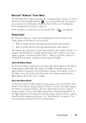
...charge gauge, press and hold the status button on the battery charge gauge for more information about the Power Meter, see "Configuring Power Management Settings" on the battery, you should consider replacing the battery. Each light represents incremental degradation. For example, if four... of the lights are on page 167 for at least 3 seconds. See "Specifications" on , the battery has 80 percent of times it...
...charge gauge, press and hold the status button on the battery charge gauge for more information about the Power Meter, see "Configuring Power Management Settings" on the battery, you should consider replacing the battery. Each light represents incremental degradation. For example, if four... of the lights are on page 167 for at least 3 seconds. See "Specifications" on , the battery has 80 percent of times it...
Owner's Manual
Page 59
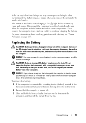
Then connect the computer to an electrical outlet to work with your Dell™ computer; For more information about resolving problems with a compatible battery purchased from Dell. NOTICE: If you choose to replace the battery with your docking device for instructions. 2 Ensure that the computer is turned off the computer, disconnect the AC adapter from the...
Then connect the computer to an electrical outlet to work with your Dell™ computer; For more information about resolving problems with a compatible battery purchased from Dell. NOTICE: If you choose to replace the battery with your docking device for instructions. 2 Ensure that the computer is turned off the computer, disconnect the AC adapter from the...
Owner's Manual
Page 60
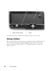
A battery discharges during prolonged storage. Storing a Battery Remove the battery when you use it. 60 Using a Battery After a long storage period, recharge the battery fully (see "Charging the Battery" on page 58) before you store your computer for an extended period of time. 1 2 1 battery-bay latch release 2 battery To replace the battery, follow the removal procedure in reverse order.
A battery discharges during prolonged storage. Storing a Battery Remove the battery when you use it. 60 Using a Battery After a long storage period, recharge the battery fully (see "Charging the Battery" on page 58) before you store your computer for an extended period of time. 1 2 1 battery-bay latch release 2 battery To replace the battery, follow the removal procedure in reverse order.
Owner's Manual
Page 90
...and hold the power button for several seconds until the computer turns off . Do not use only the battery designed for other Dell computers. 90 Adding and Replacing Parts If your computer and attached devices did not automatically turn off your warranty. As you shut down ... in the Product Information Guide. NOTICE: To disconnect a network cable, first unplug the cable from the battery bay before you begin any of cable, press in this particular Dell computer. NOTICE: Only a certified service technician should perform repairs on the locking tabs before you connect a...
...and hold the power button for several seconds until the computer turns off . Do not use only the battery designed for other Dell computers. 90 Adding and Replacing Parts If your computer and attached devices did not automatically turn off your warranty. As you shut down ... in the Product Information Guide. NOTICE: To disconnect a network cable, first unplug the cable from the battery bay before you begin any of cable, press in this particular Dell computer. NOTICE: Only a certified service technician should perform repairs on the locking tabs before you connect a...
Owner's Manual
Page 91
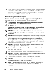
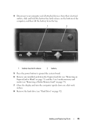
4 Disconnect your computer and all attached devices from their electrical outlets, slide and hold the battery-bay latch release on the bottom of the computer, and then lift the battery from the bay. 1 2 1 battery-bay latch release 2 battery 5 Press the power button to ground the system board. 6 Remove any installed cards from the ExpressCard slot...). 7 Close the display and turn the computer upside down on a flat work surface. 8 Remove the hard drive (see "Hard Drive" on page 92). Adding and Replacing Parts 91
4 Disconnect your computer and all attached devices from their electrical outlets, slide and hold the battery-bay latch release on the bottom of the computer, and then lift the battery from the bay. 1 2 1 battery-bay latch release 2 battery 5 Press the power button to ground the system board. 6 Remove any installed cards from the ExpressCard slot...). 7 Close the display and turn the computer upside down on a flat work surface. 8 Remove the hard drive (see "Hard Drive" on page 92). Adding and Replacing Parts 91
Owner's Manual
Page 97
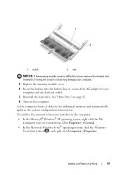
Forcing the cover to close may damage your computer. 5 Replace the memory module cover. 6 Insert the battery into the battery bay, or connect the AC adapter to close, remove the module and reinstall it detects the additional memory and automatically updates the system configuration ... installed in the computer: • In the Microsoft® Windows® XP operating system, right-click the My Computer icon on the computer. Adding and Replacing Parts 97 See "Hard Drive" on page 92. 8 Turn on your computer and an electrical outlet. 7 Reinstall the hard drive. 1 2 1 notch 2 tab NOTICE: ...
Forcing the cover to close may damage your computer. 5 Replace the memory module cover. 6 Insert the battery into the battery bay, or connect the AC adapter to close, remove the module and reinstall it detects the additional memory and automatically updates the system configuration ... installed in the computer: • In the Microsoft® Windows® XP operating system, right-click the My Computer icon on the computer. Adding and Replacing Parts 97 See "Hard Drive" on page 92. 8 Turn on your computer and an electrical outlet. 7 Reinstall the hard drive. 1 2 1 notch 2 tab NOTICE: ...

Owner's Manual
Page 100
... the display all the way (180 degrees) so that it . NOTICE: To help prevent damage to the system board, you must remove the battery from the battery bay before you begin working inside the computer. 1 Follow the procedures in the Product Information Guide. c Ease the hinge cover up, moving from... left , and remove it lies flat against your work surface. NOTE: When replacing the hinge cover, first insert the left edge and then ...
... the display all the way (180 degrees) so that it . NOTICE: To help prevent damage to the system board, you must remove the battery from the battery bay before you begin working inside the computer. 1 Follow the procedures in the Product Information Guide. c Ease the hinge cover up, moving from... left , and remove it lies flat against your work surface. NOTE: When replacing the hinge cover, first insert the left edge and then ...

Owner's Manual
Page 101
...yourself by using a wrist grounding strap or by periodically touching an unpainted metal surface (such as a connector on page 100. Adding and Replacing Parts 101 See "Hinge Cover" on the back of the procedures in this section, follow the safety instructions in "Before You Begin" ...page 89. 2 Open the display. 3 Remove the hinge cover. NOTICE: To help prevent damage to the system board, you must remove the battery from the battery bay before you begin working inside the computer. 1 Follow the procedures in the Product Information Guide. 1 2 1 hinge cover 2 scribe Keyboard ...
...yourself by using a wrist grounding strap or by periodically touching an unpainted metal surface (such as a connector on page 100. Adding and Replacing Parts 101 See "Hinge Cover" on the back of the procedures in this section, follow the safety instructions in "Before You Begin" ...page 89. 2 Open the display. 3 Remove the hinge cover. NOTICE: To help prevent damage to the system board, you must remove the battery from the battery bay before you begin working inside the computer. 1 Follow the procedures in the Product Information Guide. 1 2 1 hinge cover 2 scribe Keyboard ...

Owner's Manual
Page 103
...ordered a Mini-Card with your computer, the card is not already installed, go to the system board, you must remove the battery from the battery bay before you are replacing a Mini-Card, remove the existing card: a Disconnect the two antenna cables from the Mini-Card. 1 1 Mini-Card 2... 2 antenna cable connectors (2) Adding and Replacing Parts 103 CAUTION: Before you begin working inside the computer. 1 Follow the procedures in the ...
...ordered a Mini-Card with your computer, the card is not already installed, go to the system board, you must remove the battery from the battery bay before you are replacing a Mini-Card, remove the existing card: a Disconnect the two antenna cables from the Mini-Card. 1 1 Mini-Card 2... 2 antenna cable connectors (2) Adding and Replacing Parts 103 CAUTION: Before you begin working inside the computer. 1 Follow the procedures in the ...

Owner's Manual
Page 106
... "Before You Begin" on page 89. 2 Remove the hinge cover. See "Hinge Cover" on page 101. 106 Adding and Replacing Parts 1 2 1 system board connector 2 antenna cables (2) 3 antenna cable connectors (2) Coin-Cell Battery CAUTION: Before you begin any of the computer). NOTICE: To help prevent damage to the system board, you must remove...
... "Before You Begin" on page 89. 2 Remove the hinge cover. See "Hinge Cover" on page 101. 106 Adding and Replacing Parts 1 2 1 system board connector 2 antenna cables (2) 3 antenna cable connectors (2) Coin-Cell Battery CAUTION: Before you begin any of the computer). NOTICE: To help prevent damage to the system board, you must remove...

Owner's Manual
Page 107
...procedures in this section, follow the safety instructions in "Before You Begin" on the back). 4 Disconnect the antenna cables from the battery bay before you replace the battery, insert it at a 30-degree angle under the clip with the positive (identified by periodically touching an unpainted metal surface (such as... that secure the display (two on the top, two on the bottom, and two on page 89. 2 Remove the hinge cover. Adding and Replacing Parts 107 NOTICE: To avoid electrostatic discharge, ground yourself by using a wrist grounding strap or by a plus [+] symbol) side up, and then...
...procedures in this section, follow the safety instructions in "Before You Begin" on the back). 4 Disconnect the antenna cables from the battery bay before you replace the battery, insert it at a 30-degree angle under the clip with the positive (identified by periodically touching an unpainted metal surface (such as... that secure the display (two on the top, two on the bottom, and two on page 89. 2 Remove the hinge cover. Adding and Replacing Parts 107 NOTICE: To avoid electrostatic discharge, ground yourself by using a wrist grounding strap or by a plus [+] symbol) side up, and then...
Owner's Manual
Page 128
...Product Information Guide. Also, for Mobile Broadband (WWAN) ExpressCards, see "Dell Diagnostics" on page 135. The keyboard controller may be malfunctioning, or a memory module may appear. Replace the battery, or connect the computer to continue the desired action. ENSURE THAT ... tests and the Keyboard Controller test in the Product Information Guide. Some cards do not support this Windows feature, the card will be loose. The battery is properly inserted into the drive and try again. If your administrator to an electrical outlet; U N E X P E C T E D I N T E R R U P T I...
...Product Information Guide. Also, for Mobile Broadband (WWAN) ExpressCards, see "Dell Diagnostics" on page 135. The keyboard controller may be malfunctioning, or a memory module may appear. Replace the battery, or connect the computer to continue the desired action. ENSURE THAT ... tests and the Keyboard Controller test in the Product Information Guide. Some cards do not support this Windows feature, the card will be loose. The battery is properly inserted into the drive and try again. If your administrator to an electrical outlet; U N E X P E C T E D I N T E R R U P T I...

Owner's Manual
Page 203
...55 charging, 58 checking the charge, 54 conserving power, 56 description, 30 performance, 53 power meter, 55 removing, 59 replacing coin-cell battery, 106 storing, 60 battery-bay latch release, 29 blanks ExpressCards, 69 removing, 71, 73 boot sequence, 178 brightness adjusting, 41 C CardBus technology ...drive problems, 119 CDs, 63 about, 63 operating system, 18 playing, 61 Check Disk, 120 cleaning touch pad, 180 coin-cell battery replacing, 106 computer crashes, 131-132 protecting, 86 restore to previous operating state, 154 slow performance, 122, 133 specifications, 167 stops responding...
...55 charging, 58 checking the charge, 54 conserving power, 56 description, 30 performance, 53 power meter, 55 removing, 59 replacing coin-cell battery, 106 storing, 60 battery-bay latch release, 29 blanks ExpressCards, 69 removing, 71, 73 boot sequence, 178 brightness adjusting, 41 C CardBus technology ...drive problems, 119 CDs, 63 about, 63 operating system, 18 playing, 61 Check Disk, 120 cleaning touch pad, 180 coin-cell battery replacing, 106 computer crashes, 131-132 protecting, 86 restore to previous operating state, 154 slow performance, 122, 133 specifications, 167 stops responding...
Service Manual
Page 2
... Assembly 1. Remove the hard drive (see Removing the System Board). 9. Remove the spring from the battery latch assembly. NOTICE: To help prevent damage to Contents Page Battery Latch Assembly Dell™ Latitude™ 131L/ Dell Vostro™ 1000 Service Manual Removing the Battery Latch Assembly Replacing the Battery Latch Assembly CAUTION: Before you remove the M2 x 2.7-mm screw, the...
... Assembly 1. Remove the hard drive (see Removing the System Board). 9. Remove the spring from the battery latch assembly. NOTICE: To help prevent damage to Contents Page Battery Latch Assembly Dell™ Latitude™ 131L/ Dell Vostro™ 1000 Service Manual Removing the Battery Latch Assembly Replacing the Battery Latch Assembly CAUTION: Before you remove the M2 x 2.7-mm screw, the...

Service Manual
Page 3
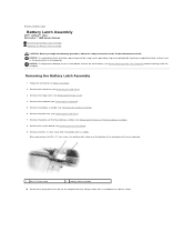
...that the newly installed latch moves smoothly and freely when pushed and released. 4. Replace the display assembly (see Replacing the Palm Rest). 7. Replace the keyboard (see Replacing the Hinge Cover). 10. Place the battery latch release under the computer base, line it out of the channel and away ...from the computer base. 1 battery latch assembly Replacing the Battery Latch Assembly 1. Remove the plastic battery-latch assembly by twisting the assembly slightly and lifting it up with the hole in the base, and then replace the screw in the assembly. Insert the latch...
...that the newly installed latch moves smoothly and freely when pushed and released. 4. Replace the display assembly (see Replacing the Palm Rest). 7. Replace the keyboard (see Replacing the Hinge Cover). 10. Place the battery latch release under the computer base, line it out of the channel and away ...from the computer base. 1 battery latch assembly Replacing the Battery Latch Assembly 1. Remove the plastic battery-latch assembly by twisting the assembly slightly and lifting it up with the hole in the base, and then replace the screw in the assembly. Insert the latch...
Service Manual
Page 7
... prevent damage to the system board, you must remove the battery from the battery bay before you begin working inside the computer. Disconnect the Bluetooth cable. 6. Back to Contents Page Bluetooth® Card Dell™ Latitude™ 131L/ Dell Vostro™ 1000 Service Manual Removing a Bluetooth Card Replacing a Bluetooth Card CAUTION: Before you begin any of the...
... prevent damage to the system board, you must remove the battery from the battery bay before you begin working inside the computer. Disconnect the Bluetooth cable. 6. Back to Contents Page Bluetooth® Card Dell™ Latitude™ 131L/ Dell Vostro™ 1000 Service Manual Removing a Bluetooth Card Replacing a Bluetooth Card CAUTION: Before you begin any of the...
Service Manual
Page 8
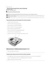
... board, remove the main battery (see Removing the Display Assembly). 7. Replacing the ExpressCard/Hard-Drive Bay Assembly 1. NOTICE: To help prevent damage to Contents Page ExpressCard/Hard-Drive Bay Assembly Dell™ Latitude™ 131L/ Dell Vostro™ 1000 Service Manual Removing the ExpressCard.../Hard-Drive Bay Assembly Replacing the ExpressCard/Hard-Drive Bay Assembly CAUTION: Before you begin the following ...
... board, remove the main battery (see Removing the Display Assembly). 7. Replacing the ExpressCard/Hard-Drive Bay Assembly 1. NOTICE: To help prevent damage to Contents Page ExpressCard/Hard-Drive Bay Assembly Dell™ Latitude™ 131L/ Dell Vostro™ 1000 Service Manual Removing the ExpressCard.../Hard-Drive Bay Assembly Replacing the ExpressCard/Hard-Drive Bay Assembly CAUTION: Before you begin the following ...


