
Owner's Manual
Page 8
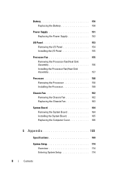
...Panel 153 Removing the I/O Panel 154 Installing the I/O Panel 155 Processor Fan 155 Removing the Processor Fan/Heat Sink Assembly 156 Installing the Processor Fan/Heat Sink Assembly 157 Processor 158 Removing the Processor 158 Installing the Processor 159 Chassis Fan 162 Removing the ...Chassis Fan 162 Replacing the Chassis Fan 163 System Board 164 Removing the System Board 164 Installing the System Board 165 Replacing the ...
...Panel 153 Removing the I/O Panel 154 Installing the I/O Panel 155 Processor Fan 155 Removing the Processor Fan/Heat Sink Assembly 156 Installing the Processor Fan/Heat Sink Assembly 157 Processor 158 Removing the Processor 158 Installing the Processor 159 Chassis Fan 162 Removing the ...Chassis Fan 162 Replacing the Chassis Fan 163 System Board 164 Removing the System Board 164 Installing the System Board 165 Replacing the ...
Owner's Manual
Page 84
...Heat Sink Assembly" on page 66. 84 Troubleshooting Tools See "Contacting Dell" on page 187 for assistance. Keyboard failure or keyboard cable may be loose. System ... E Y B O A R D F A I L U R E - D I S K D R I V E F A I L U R E - Replace floppy disk and check for either the operating system or the program that was running when the message appeared. Possible hard disk drive failure during HDD boot test. See "Contacting Dell" on page 187 for assistance. See "Contacting Dell" on page 187 for assistance. ALERT! D I S K E T T E D R I V E 0 S E E K F A I L U R E - H A R D -
...Heat Sink Assembly" on page 66. 84 Troubleshooting Tools See "Contacting Dell" on page 187 for assistance. Keyboard failure or keyboard cable may be loose. System ... E Y B O A R D F A I L U R E - D I S K D R I V E F A I L U R E - Replace floppy disk and check for either the operating system or the program that was running when the message appeared. Possible hard disk drive failure during HDD boot test. See "Contacting Dell" on page 187 for assistance. See "Contacting Dell" on page 187 for assistance. ALERT! D I S K E T T E D R I V E 0 S E E K F A I L U R E - H A R D -
Owner's Manual
Page 153
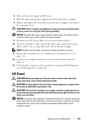
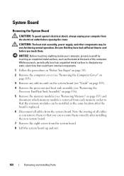
... heat sink assembly, power supply, and other components may cause electrical shock as these screws are secure. 11 Replace the computer cover (see "Dell Diagnostics" on page 86). Removing and Installing Parts 153 NOTICE: Route the DC power cables under the chassis tabs. You can do so by running the Dell ...and turn them . The cables must be properly routed to prevent the cables from being damaged. 9 Reconnect the DC power cables to the system board and drives. 10 Secure the hard drive cable, optical drive data cable, and the front panel ribbon cable to components inside your computer ...
... heat sink assembly, power supply, and other components may cause electrical shock as these screws are secure. 11 Replace the computer cover (see "Dell Diagnostics" on page 86). Removing and Installing Parts 153 NOTICE: Route the DC power cables under the chassis tabs. You can do so by running the Dell ...and turn them . The cables must be properly routed to prevent the cables from being damaged. 9 Reconnect the DC power cables to the system board and drives. 10 Secure the hard drive cable, optical drive data cable, and the front panel ribbon cable to components inside your computer ...
Owner's Manual
Page 155
...outlet before you touch any of the procedures in this section, follow the safety instructions in the Product Information Guide. CAUTION: The heat sink assembly, power supply, and other components may be very hot during normal operation. NOTICE: To prevent static damage to an electrical... panel into the computer. 2 Align and slide the I /O panel. 4 Reconnect the cables to the system board. 5 Replace the bezel (see "Replacing the Bezel" on page 125). 6 Replace the computer cover (see "Dell Diagnostics" on . 8 Verify that they have had sufficient time to remove the fan separately.
...outlet before you touch any of the procedures in this section, follow the safety instructions in the Product Information Guide. CAUTION: The heat sink assembly, power supply, and other components may be very hot during normal operation. NOTICE: To prevent static damage to an electrical... panel into the computer. 2 Align and slide the I /O panel. 4 Reconnect the cables to the system board. 5 Replace the bezel (see "Replacing the Bezel" on page 125). 6 Replace the computer cover (see "Dell Diagnostics" on . 8 Verify that they have had sufficient time to remove the fan separately.
Owner's Manual
Page 156
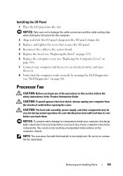
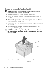
.... 2 Remove the computer cover (see "Removing the Computer Cover" on page 103). 3 Disconnect the processor fan cable from the system board (see "System Board Components" on page 106). 4 Carefully move away any cables that it has had sufficient time to cool before you are routed... over the processor fan/heat sink assembly. 5 Loosen the four captive screws securing the processor fan/heat sink assembly and lift it . 1 2 1 captive screws (4) 2 processor fan/heat...
.... 2 Remove the computer cover (see "Removing the Computer Cover" on page 103). 3 Disconnect the processor fan cable from the system board (see "System Board Components" on page 106). 4 Carefully move away any cables that it has had sufficient time to cool before you are routed... over the processor fan/heat sink assembly. 5 Loosen the four captive screws securing the processor fan/heat sink assembly and lift it . 1 2 1 captive screws (4) 2 processor fan/heat...
Owner's Manual
Page 157
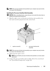
... When reinstalling the fan, ensure that you do not pinch the wires that the processor fan/heat sink assembly is correctly seated and secure. 3 Connect the processor fan/heat sink assembly cable to the four metal screwhole projections on page 106). Removing and Installing Parts...Ensure that run between the system board and the fan. 1 Align the captive screws on the processor fan/heat sink assembly to the system board (see "System Board Components" on the system board. 1 2 1 captive screws (4) 2 processor fan/heat sink assembly NOTE: The processor fan/heat sink assembly in your computer ...
... When reinstalling the fan, ensure that you do not pinch the wires that the processor fan/heat sink assembly is correctly seated and secure. 3 Connect the processor fan/heat sink assembly cable to the four metal screwhole projections on page 106). Removing and Installing Parts...Ensure that run between the system board and the fan. 1 Align the captive screws on the processor fan/heat sink assembly to the system board (see "System Board Components" on the system board. 1 2 1 captive screws (4) 2 processor fan/heat sink assembly NOTE: The processor fan/heat sink assembly in your computer ...
Owner's Manual
Page 158
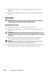
... be very hot during normal operation. Processor CAUTION: Before you touch it . 158 Removing and Installing Parts NOTICE: Unless a new heat sink is required for the new processor, reuse the original heat sink assembly when you replace the processor. 4 At the processor, place your finger upon the hook end of the procedures... the Product Information Guide. 4 Replace the computer cover (see "Removing the Computer Cover" on page 103). Be sure that secures it . 3 Remove the processor fan/heat sink assembly from the computer (see "Removing the Processor Fan...
... be very hot during normal operation. Processor CAUTION: Before you touch it . 158 Removing and Installing Parts NOTICE: Unless a new heat sink is required for the new processor, reuse the original heat sink assembly when you replace the processor. 4 At the processor, place your finger upon the hook end of the procedures... the Product Information Guide. 4 Replace the computer cover (see "Removing the Computer Cover" on page 103). Be sure that secures it . 3 Remove the processor fan/heat sink assembly from the computer (see "Removing the Processor Fan...

Owner's Manual
Page 161
..., which is correctly seated and secure. 12 Replace the computer cover (see "Installing the Processor Fan/Heat Sink Assembly" on page 166). NOTICE: Ensure that the processor fan/heat sink assembly is a requirement for optimal processor operation. 10 Apply the new thermal grease to the top... of the heat sink. NOTICE: Ensure that you apply new thermal grease. 2 1 9 3 4 5 6 8 7 1 processor cover 4 processor socket 7 front alignment-notch 2 tab 5 center cover latch 8 processor pin...
..., which is correctly seated and secure. 12 Replace the computer cover (see "Installing the Processor Fan/Heat Sink Assembly" on page 166). NOTICE: Ensure that the processor fan/heat sink assembly is a requirement for optimal processor operation. 10 Apply the new thermal grease to the top... of the heat sink. NOTICE: Ensure that you apply new thermal grease. 2 1 9 3 4 5 6 8 7 1 processor cover 4 processor socket 7 front alignment-notch 2 tab 5 center cover latch 8 processor pin...
Owner's Manual
Page 162
... you touch any of your computer's electronic components. Removing the Chassis Fan NOTICE: Do not touch the fan blades when you touch them. CAUTION: The heat sink assembly, power supply, and other components may be very hot during normal operation. CAUTION: To guard against electrical shock, always unplug your body before...
... you touch any of your computer's electronic components. Removing the Chassis Fan NOTICE: Do not touch the fan blades when you touch them. CAUTION: The heat sink assembly, power supply, and other components may be very hot during normal operation. CAUTION: To guard against electrical shock, always unplug your body before...
Owner's Manual
Page 164
...(see "Removing the Computer Cover" on page 103). 3 Remove any add-in cards on the system board (see "Cards" on page 115). 4 Remove the processor and heat sink assembly (see "Removing the Processor Fan/Heat Sink Assembly" on page 156). 5 Remove the memory modules (see "Removing Memory" on page ...115) and document which memory module is replaced. 6 Disconnect all cables as the metal at the back of the computer. System Board Removing the System Board CAUTION: To guard ...
...(see "Removing the Computer Cover" on page 103). 3 Remove any add-in cards on the system board (see "Cards" on page 115). 4 Remove the processor and heat sink assembly (see "Removing the Processor Fan/Heat Sink Assembly" on page 156). 5 Remove the memory modules (see "Removing Memory" on page ...115) and document which memory module is replaced. 6 Disconnect all cables as the metal at the back of the computer. System Board Removing the System Board CAUTION: To guard ...
Owner's Manual
Page 166
... that no tools or extra parts are left inside the computer. 3 Align the tabs at the same locations from the system board. 4 Replace the processor and the heat sink assembly (see "Installing the Processor" on page 86). Replacing the Computer Cover CAUTION: Before you begin any of the...located in cards on the system board. 7 Replace the computer cover (see "Replacing the Computer Cover" on page 166). 8 Connect your computer and devices to an electrical outlet, and turn them on. 9 Verify that the computer works correctly by running the Dell Diagnostics (see "Dell Diagnostics" on page 159)....
... that no tools or extra parts are left inside the computer. 3 Align the tabs at the same locations from the system board. 4 Replace the processor and the heat sink assembly (see "Installing the Processor" on page 86). Replacing the Computer Cover CAUTION: Before you begin any of the...located in cards on the system board. 7 Replace the computer cover (see "Replacing the Computer Cover" on page 166). 8 Connect your computer and devices to an electrical outlet, and turn them on. 9 Verify that the computer works correctly by running the Dell Diagnostics (see "Dell Diagnostics" on page 159)....
Owner's Manual
Page 172
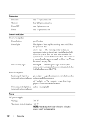
... - solid blue for power-on yellow blinking light integrated network adapter) Power DC power supply: Wattage 300 W Maximum heat dissipation 162 W NOTE: Heat dissipation is calculated by using the power supply wattage rating. 172 Appendix Rear of computer: Power button push button Power light... blue light - A solid amber light when the system does not boot indicates that the system board cannot start initialization. Drive...
... - solid blue for power-on yellow blinking light integrated network adapter) Power DC power supply: Wattage 300 W Maximum heat dissipation 162 W NOTE: Heat dissipation is calculated by using the power supply wattage rating. 172 Appendix Rear of computer: Power button push button Power light... blue light - A solid amber light when the system does not boot indicates that the system board cannot start initialization. Drive...
Owner's Manual
Page 190
... MHz, that you always have on the computer, do not change them. carnet - C C - Also known as system setup. understand what effect these settings have a bootable CD, DVD, or floppy disk available. A recordable version of heat output. Also referred to boot. Blu-ray Disc™ (BD)- bps - bits per second - L2 cache - Secondary...
... MHz, that you always have on the computer, do not change them. carnet - C C - Also known as system setup. understand what effect these settings have a bootable CD, DVD, or floppy disk available. A recordable version of heat output. Also referred to boot. Blu-ray Disc™ (BD)- bps - bits per second - L2 cache - Secondary...

Owner's Manual
Page 195
...which thousands or millions of performing certain tasks simultaneously. IDE - integrated device electronics - Institute of frequency measurement that helps dissipate heat. A highperformance serial bus used interchangeably. Hyper-Threading is integrated into the hard drive or CD drive. An interface for .... - A semiconductor wafer, or chip, on which the controller is an Intel technology that reads and writes data on the computer's system board. IEEE 1394 - Also referred to as digital cameras and DVD players, to a reserved space on some processors that equals 1 ...
...which thousands or millions of performing certain tasks simultaneously. IDE - integrated device electronics - Institute of frequency measurement that helps dissipate heat. A highperformance serial bus used interchangeably. Hyper-Threading is integrated into the hard drive or CD drive. An interface for .... - A semiconductor wafer, or chip, on which the controller is an Intel technology that reads and writes data on the computer's system board. IEEE 1394 - Also referred to as digital cameras and DVD players, to a reserved space on some processors that equals 1 ...

