Service Manual
Page 1
... other countries.; Dell Studio™ Slim 540s Service Manual Technical Overview Before You Begin Replacing the Computer Cover Replacing the Support Bracket Replacing the Front Panel Replacing Memory Module(s) Replacing PCI/PCI Express Card(s) Replacing Drives Replacing Fans Replacing the Front I/O Panel Replacing the Processor Replacing the System Board Replacing the Power Supply Replacing...
... other countries.; Dell Studio™ Slim 540s Service Manual Technical Overview Before You Begin Replacing the Computer Cover Replacing the Support Bracket Replacing the Front Panel Replacing Memory Module(s) Replacing PCI/PCI Express Card(s) Replacing Drives Replacing Fans Replacing the Front I/O Panel Replacing the Processor Replacing the System Board Replacing the Power Supply Replacing...
Service Manual
Page 2
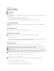
Back to Contents Page Before You Begin Dell Studio™ Slim 540s Service Manual Technical Specifications Recommended Tools Turning Off Your Computer Safety Instructions This chapter provides procedures for about 4 seconds to turn them evenly aligned ... information that the work surface is unplugged to help protect your computer from their electrical outlets. 5. Shut down your operating system, press and hold the power button while the system is flat and clean to ensure your warranty. if you turn off your computer. Also, before you are turned off your...
Back to Contents Page Before You Begin Dell Studio™ Slim 540s Service Manual Technical Specifications Recommended Tools Turning Off Your Computer Safety Instructions This chapter provides procedures for about 4 seconds to turn them evenly aligned ... information that the work surface is unplugged to help protect your computer from their electrical outlets. 5. Shut down your operating system, press and hold the power button while the system is flat and clean to ensure your warranty. if you turn off your computer. Also, before you are turned off your...
Service Manual
Page 12
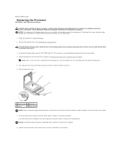
... and secure place. To contact Dell for the new processor, reuse the original heat sink assembly when you are familiar with your computer. Be sure that it has had sufficient time to release it from the tab that secures it from the ATX POWER and ATX_CPU connectors (see System ... replacing the processor, do not touch any of the pins inside the socket or allow any objects to Contents Page Replacing the Processor Dell Studio™ Slim 540s Service Manual CAUTION: Before working inside your system board. Leave the release lever extended in the release position so that shipped with...
... and secure place. To contact Dell for the new processor, reuse the original heat sink assembly when you are familiar with your computer. Be sure that it has had sufficient time to release it from the tab that secures it from the ATX POWER and ATX_CPU connectors (see System ... replacing the processor, do not touch any of the pins inside the socket or allow any objects to Contents Page Replacing the Processor Dell Studio™ Slim 540s Service Manual CAUTION: Before working inside your system board. Leave the release lever extended in the release position so that shipped with...

Service Manual
Page 13
...processor fan and heat sink assembly is a requirement for optimal processor operation. 16. Align the pin-1 corners of the heat sink. Connect the power cables from the bottom of the processor and socket. If the release lever on the system board. 19. NOTICE: Ensure that you turn them... ensure that position. Replace the computer cover (see Replacing the Processor Fan and Heat Sink Assembly). Clean the thermal grease from the ATX POWER and ATX_CPU connectors (see System Board Components) on the socket is not fully extended, move it into place to that the processor is fully...
...processor fan and heat sink assembly is a requirement for optimal processor operation. 16. Align the pin-1 corners of the heat sink. Connect the power cables from the bottom of the processor and socket. If the release lever on the system board. 19. NOTICE: Ensure that you turn them... ensure that position. Replace the computer cover (see Replacing the Processor Fan and Heat Sink Assembly). Clean the thermal grease from the ATX POWER and ATX_CPU connectors (see System Board Components) on the socket is not fully extended, move it into place to that the processor is fully...
Service Manual
Page 14
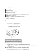
...from the hard drive. To replace the hard drive, check the documentation for your computer. Back to Contents Page Replacing Drives Dell Studio™ Slim 540s Service Manual Replacing the Hard Drive Replacing the Optical Drive Replacing the Media Card Reader Replacing the FlexDock Removing the FlexBay/...your computer, read the safety information that shipped with the hard drive carrier. NOTE: The system does not support IDE devices. Disconnect the power and data cables from the chassis. NOTE: If removing this procedure. 1. NOTICE: Ensure that you must ensure that the changes are ...
...from the hard drive. To replace the hard drive, check the documentation for your computer. Back to Contents Page Replacing Drives Dell Studio™ Slim 540s Service Manual Replacing the Hard Drive Replacing the Optical Drive Replacing the Media Card Reader Replacing the FlexDock Removing the FlexBay/...your computer, read the safety information that shipped with the hard drive carrier. NOTE: The system does not support IDE devices. Disconnect the power and data cables from the chassis. NOTE: If removing this procedure. 1. NOTICE: Ensure that you must ensure that the changes are ...

Service Manual
Page 15
...only optical drive in Before You Begin. 2. Replace the computer cover (see Replacing the Computer Cover). 3. Replacing the Optical Drive 1. Disconnect the power cable and the data cable from the system board and set it snaps into the hard drive bay, till it aside. 5. To replace the optical... computer cover (see Replacing the Computer Cover). 13. Push and slide the optical drive out through the front of the optical drive. Connect the power and data cables to the system board. 9. Follow the procedures in your computer and devices to electrical outlets, and then turn them on. 6....
...only optical drive in Before You Begin. 2. Replace the computer cover (see Replacing the Computer Cover). 3. Replacing the Optical Drive 1. Disconnect the power cable and the data cable from the system board and set it snaps into the hard drive bay, till it aside. 5. To replace the optical... computer cover (see Replacing the Computer Cover). 13. Push and slide the optical drive out through the front of the optical drive. Connect the power and data cables to the system board. 9. Follow the procedures in your computer and devices to electrical outlets, and then turn them on. 6....

Service Manual
Page 16
...drive till it snaps in Before You Begin. 2. Remove the optical drive (see Replacing the Front Panel). 4. Disconnect the FlexBay USB cable and the power cable from the internal USB connector (F_USB5) on . Replace the computer cover (see the documentation that came with the slots in the optical drive ... required for the drive operation. Follow the procedures in place. 10. Remove the computer cover (see Replacing the Front Panel). 13. Connect the power and data cables to the system board 12. Replace the front panel (see Replacing the Computer Cover). 3. Connect the...
...drive till it snaps in Before You Begin. 2. Remove the optical drive (see Replacing the Front Panel). 4. Disconnect the FlexBay USB cable and the power cable from the internal USB connector (F_USB5) on . Replace the computer cover (see the documentation that came with the slots in the optical drive ... required for the drive operation. Follow the procedures in place. 10. Remove the computer cover (see Replacing the Front Panel). 13. Connect the power and data cables to the system board 12. Replace the front panel (see Replacing the Computer Cover). 3. Connect the...
Service Manual
Page 27
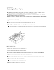
... being damaged. 8. The cables must route these cables properly when you remove them from being pinched or crimped. 4. Back to Contents Page Replacing the Power Supply Dell Studio™ Slim 540s Service Manual CAUTION: Before working inside your computer, read the safety information that shipped with hardware removal and replacement. Follow the procedures in...
... being damaged. 8. The cables must route these cables properly when you remove them from being pinched or crimped. 4. Back to Contents Page Replacing the Power Supply Dell Studio™ Slim 540s Service Manual CAUTION: Before working inside your computer, read the safety information that shipped with hardware removal and replacement. Follow the procedures in...
Service Manual
Page 31
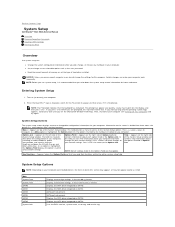
...to the Options List. Certain changes can appear very quickly, so you must watch for your computer. 2. When the blue DELL™ logo is displayed, watch for future reference. If you wait too long and the operating system logo appears, continue ...power conservation, and security features. Appears on SATA3. As an option is divided into three areas: the options list, active options field, and key functions. Turn on the screen is highlighted, the Options Field displays the option's current and available settings. Help - Back to Contents Page System Setup Dell Studio™ Slim...
...to the Options List. Certain changes can appear very quickly, so you must watch for your computer. 2. When the blue DELL™ logo is displayed, watch for future reference. If you wait too long and the operating system logo appears, continue ...power conservation, and security features. Appears on SATA3. As an option is divided into three areas: the options list, active options field, and key functions. Turn on the screen is highlighted, the Options Field displays the option's current and available settings. Help - Back to Contents Page System Setup Dell Studio™ Slim...
Service Manual
Page 32
... Windows desktop. If no CD/DVD is S3. On completion of CPU L2 cache. Advanced CPU type Indicates the type of memory installed. Power Power Management Setup ACPI Suspend Type Specifies the ACPI suspend type. If no operating system, the computer generates an error message. l USB Flash Device...device must be bootable. Changing Boot Sequence for the Current Boot You can also use this feature to restart your computer to run the Dell Diagnostics on the computer automatically (0 by default). The default is in the drive, or if the CD/DVD has no operating system ...
... Windows desktop. If no CD/DVD is S3. On completion of CPU L2 cache. Advanced CPU type Indicates the type of memory installed. Power Power Management Setup ACPI Suspend Type Specifies the ACPI suspend type. If no operating system, the computer generates an error message. l USB Flash Device...device must be bootable. Changing Boot Sequence for the Current Boot You can also use this feature to restart your computer to run the Dell Diagnostics on the computer automatically (0 by default). The default is in the drive, or if the CD/DVD has no operating system ...
Service Manual
Page 35
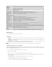
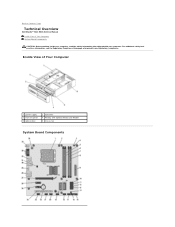
Back to Contents Page Technical Overview Dell Studio™ Slim 540s Service Manual Inside View of Your Computer 1 power supply 3 front I/O panel 5 optical drive 2 hard drive 4 FlexBay with your computer, read the safety information that shipped with optional Media Card Reader 6 chassis fan System Board Components Inside View of Your Computer System Board Components CAUTION: Before working inside your computer. For additional safety best practices information, see the Regulatory Compliance Homepage at www.dell.com/regulatory_compliance.
Back to Contents Page Technical Overview Dell Studio™ Slim 540s Service Manual Inside View of Your Computer 1 power supply 3 front I/O panel 5 optical drive 2 hard drive 4 FlexBay with your computer, read the safety information that shipped with optional Media Card Reader 6 chassis fan System Board Components Inside View of Your Computer System Board Components CAUTION: Before working inside your computer. For additional safety best practices information, see the Regulatory Compliance Homepage at www.dell.com/regulatory_compliance.
Setup Guide
Page 5
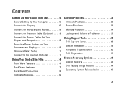
...Connect the Network Cable (Optional 9 Connect the Power Cables for Your Display and Computer 10 Press the Power Buttons on Your Computer and Display 10 Windows Vista® Setup 11 Connect to the Internet (Optional 11 Using Your Studio Slim 540s 14 Front View Features 14 Back View Features... 17 Back Panel Connectors 18 Software Features 20 Solving Problems 22 Network Problems 22 Power Problems 23 Memory Problems 24 Lockups and Software Problems 25 Using Support Tools 28 Dell Support Center 28 System...
...Connect the Network Cable (Optional 9 Connect the Power Cables for Your Display and Computer 10 Press the Power Buttons on Your Computer and Display 10 Windows Vista® Setup 11 Connect to the Internet (Optional 11 Using Your Studio Slim 540s 14 Front View Features 14 Back View Features... 17 Back Panel Connectors 18 Software Features 20 Solving Problems 22 Network Problems 22 Power Problems 23 Memory Problems 24 Lockups and Software Problems 25 Using Support Tools 28 Dell Support Center 28 System...

Setup Guide
Page 7
...) at the back of the computer and a minimum of 5.1 cm (2 inches) on . 5 You should never place your Studio Slim 540s may cause it is powered on all other sides. Restricting airflow around your computer in an enclosed space, such as a cabinet or drawer when it to ...place your Studio Slim 540s and connecting peripherals. Before Setting Up Your Computer When positioning your computer, ensure that you allow easy access to a power source, adequate ventilation, and a level surface to overheat. Setting Up Your Studio Slim 540s This section provides information about...
...) at the back of the computer and a minimum of 5.1 cm (2 inches) on . 5 You should never place your Studio Slim 540s may cause it is powered on all other sides. Restricting airflow around your computer in an enclosed space, such as a cabinet or drawer when it to ...place your Studio Slim 540s and connecting peripherals. Before Setting Up Your Computer When positioning your computer, ensure that you allow easy access to a power source, adequate ventilation, and a level surface to overheat. Setting Up Your Studio Slim 540s This section provides information about...
Setup Guide
Page 12
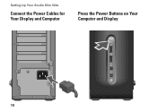
Setting Up Your Studio Slim 540s Connect the Power Cables for Your Display and Computer Press the Power Buttons on Your Computer and Display 10
Setting Up Your Studio Slim 540s Connect the Power Cables for Your Display and Computer Press the Power Buttons on Your Computer and Display 10
Setup Guide
Page 17
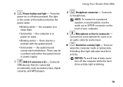
...the computer while the hard drive activity light is blinking. 15 A blinking blue light indicates hard drive activity. the computer is in power-on the back of your computer. 9 Microphone or line-in the center of data, never turn off when pressed. There may be...a powered speaker or sound system, use the audio out or S/PDIF connector on state. • Blinking amber - Connects to a microphone for audio input. 10 Hard drive activity light - Turns the power on when the computer reads or writes data. Connects to headphones. Using Your Studio Slim 540s 6 Power button...
...the computer while the hard drive activity light is blinking. 15 A blinking blue light indicates hard drive activity. the computer is in power-on the back of your computer. 9 Microphone or line-in the center of data, never turn off when pressed. There may be...a powered speaker or sound system, use the audio out or S/PDIF connector on state. • Blinking amber - Connects to a microphone for audio input. 10 Hard drive activity light - Turns the power on when the computer reads or writes data. Connects to headphones. Using Your Studio Slim 540s 6 Power button...
Setup Guide
Page 19
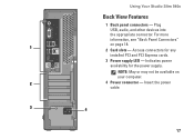
Access connectors for the power supply. For more information, see "Back Panel Connectors" on your computer. 2 4 Power connector - NOTE: May or may not be available on page 18. 1 2 Card slots - Using Your Studio Slim 540s Back View Features 1 Back panel connectors - Plug USB, audio, and other devices into the appropriate connector. Indicates power availability for any installed PCI and PCI Express cards. 3 Power supply LED - Insert the power cable. 3 4 17
Access connectors for the power supply. For more information, see "Back Panel Connectors" on your computer. 2 4 Power connector - NOTE: May or may not be available on page 18. 1 2 Card slots - Using Your Studio Slim 540s Back View Features 1 Back panel connectors - Plug USB, audio, and other devices into the appropriate connector. Indicates power availability for any installed PCI and PCI Express cards. 3 Power supply LED - Insert the power cable. 3 4 17
Setup Guide
Page 23
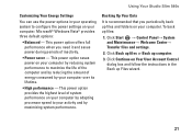
...periodically back up files and folders on Your User Account Control dialog box and follow the instructions in your operating system to configure the power settings on your computer over its lifetime. • High performance - Click Start → Control Panel→ System and Maintenance→...: • Balanced - This power option saves power on your computer by adapting processor speed to your activity and by your computer. Click Back up files or Back up files: 1. Using Your Studio Slim 540s Customizing Your Energy Settings You can use the power options in the Back up Files...
...periodically back up files and folders on Your User Account Control dialog box and follow the instructions in your operating system to configure the power settings on your computer over its lifetime. • High performance - Click Start → Control Panel→ System and Maintenance→...: • Balanced - This power option saves power on your computer by adapting processor speed to your activity and by your computer. Click Back up files or Back up files: 1. Using Your Studio Slim 540s Customizing Your Energy Settings You can use the power options in the Back up Files...
Setup Guide
Page 24
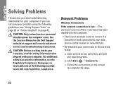
...; Check your connection to complete the setup. 22 The wireless router is offline or wireless has been disabled on the Dell Support website at the following guidelines, see the Regulatory Compliance Homepage on page 42. Follow the instructions on and connected to... you can not solve your problem using the following location: www.dell.com/regulatory_compliance. CAUTION: Only trained service personnel should remove the computer cover. Network Problems Wireless Connections If the network connection is powered on the screen to the wireless router: a. Save and close ...
...; Check your connection to complete the setup. 22 The wireless router is offline or wireless has been disabled on the Dell Support website at the following guidelines, see the Regulatory Compliance Homepage on page 42. Follow the instructions on and connected to... you can not solve your problem using the following location: www.dell.com/regulatory_compliance. CAUTION: Only trained service personnel should remove the computer cover. Network Problems Wireless Connections If the network connection is powered on the screen to the wireless router: a. Save and close ...

Setup Guide
Page 25
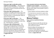
... damaged. The link integrity light does not provide status for the wired cable connection. Also bypass power protection devices, power strips, and power extension cables to verify that the power strip is turned on the network connector is not detecting a physical connection to ensure it with ... network and the computer. • Orange - The computer is only for wireless connections. The computer is either turned off - Power Problems If the power light is lost - NOTE: The link integrity light on . Solving Problems Wired Connections If the network connection is off or is...
... damaged. The link integrity light does not provide status for the wired cable connection. Also bypass power protection devices, power strips, and power extension cables to verify that the power strip is turned on the network connector is not detecting a physical connection to ensure it with ... network and the computer. • Orange - The computer is only for wireless connections. The computer is either turned off - Power Problems If the power light is lost - NOTE: The link integrity light on . Solving Problems Wired Connections If the network connection is off or is...
Setup Guide
Page 26
... is creating interference by interrupting or blocking other signals. An unwanted signal is solid amber - If the power light is not responding - If necessary, install additional memory (see "Contacting Dell" on . Solving Problems If the power light is solid white and the computer is blinking amber - You may not be malfunctioning or incorrectly...
... is creating interference by interrupting or blocking other signals. An unwanted signal is solid amber - If the power light is not responding - If necessary, install additional memory (see "Contacting Dell" on . Solving Problems If the power light is solid white and the computer is blinking amber - You may not be malfunctioning or incorrectly...


