Dell Studio 1555 Service Manual
Page 1
... notice. © 2008 Dell Inc. Dell Studio™ 1555 Service Manual Before You Begin Base Cover Hard Drive Memory Communication Cards Coin-Cell Battery Center Control Cover Keyboard Display Power Button Board Camera (Optional) Palm Rest Speaker Assembly Optical Drive ExpressCard Board AC Adapter Connector USB Connector System Board Assembly Processor Heat Sink Processor Module Fan Subwoofer Assembly Battery Latch Assembly Flashing the BIOS Notes, Cautions, and Warnings NOTE: A NOTE indicates important information that helps you make better use of Dell Inc. Model PP39L December 2008...
... notice. © 2008 Dell Inc. Dell Studio™ 1555 Service Manual Before You Begin Base Cover Hard Drive Memory Communication Cards Coin-Cell Battery Center Control Cover Keyboard Display Power Button Board Camera (Optional) Palm Rest Speaker Assembly Optical Drive ExpressCard Board AC Adapter Connector USB Connector System Board Assembly Processor Heat Sink Processor Module Fan Subwoofer Assembly Battery Latch Assembly Flashing the BIOS Notes, Cautions, and Warnings NOTE: A NOTE indicates important information that helps you make better use of Dell Inc. Model PP39L December 2008...
Dell Studio 1555 Service Manual
Page 3
... information, see Turning Off Your Computer). When connecting a cable, ensure that the work surface is not covered by its edges. l You have read the safety information that shipped with your computer. Before Working Inside Your Computer Use the following tools: l Small flat-blade screwdriver l Phillips screwdriver l Small plastic scribe l BIOS upgrade CD (see the Dell Support website at support.dell.com) Turning Off Your...
... information, see Turning Off Your Computer). When connecting a cable, ensure that the work surface is not covered by its edges. l You have read the safety information that shipped with your computer. Before Working Inside Your Computer Use the following tools: l Small flat-blade screwdriver l Phillips screwdriver l Small plastic scribe l BIOS upgrade CD (see the Dell Support website at support.dell.com) Turning Off Your...
Dell Studio 1555 Service Manual
Page 5
... setup program. 4. Follow the instructions that the main battery is installed properly. Remove the flash BIOS-update program CD from the CD. Back to Contents Page Flashing the BIOS Dell Studio™ 1555 Service Manual Flashing the BIOS From a CD Flashing the BIOS From the Hard Drive If a BIOS upgrade CD is provided with the new processor or new system board, flash the BIOS from the drive and restart the computer. Press and to prevent loss of power. The File Download window...
... setup program. 4. Follow the instructions that the main battery is installed properly. Remove the flash BIOS-update program CD from the CD. Back to Contents Page Flashing the BIOS Dell Studio™ 1555 Service Manual Flashing the BIOS From a CD Flashing the BIOS From the Hard Drive If a BIOS upgrade CD is provided with the new processor or new system board, flash the BIOS from the drive and restart the computer. Press and to prevent loss of power. The File Download window...
Dell Studio 1555 Service Manual
Page 7
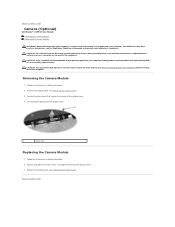
... Display Panel). Follow the instructions in Before You Begin. 2. Back to the display cover. 3. Damage due to servicing that secure the camera to the display cover. 4. Removing the Camera Module 1. Remove the two screws that is not authorized by Dell™ is not covered by periodically touching an unpainted metal surface (such as a connector on your warranty. Back to Contents Page Camera (Optional) Dell Studio™ 1555 Service Manual Removing the Camera Module Replacing the Camera Module WARNING: Before working...
... Display Panel). Follow the instructions in Before You Begin. 2. Back to the display cover. 3. Damage due to servicing that secure the camera to the display cover. 4. Removing the Camera Module 1. Remove the two screws that is not authorized by Dell™ is not covered by periodically touching an unpainted metal surface (such as a connector on your warranty. Back to Contents Page Camera (Optional) Dell Studio™ 1555 Service Manual Removing the Camera Module Replacing the Camera Module WARNING: Before working...
Dell Studio 1555 Service Manual
Page 8
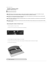
... Page Center Control Cover Dell Studio™ 1555 Service Manual Removing the Center Control Cover Replacing the Center Control Cover WARNING: Before working inside your computer, read the safety information that is not authorized by Dell™ is not covered by periodically touching an unpainted metal surface (such as possible. 4. Follow the procedures in Before You Begin. 2. Back to servicing that shipped with a plastic scribe starting from the battery bay...
... Page Center Control Cover Dell Studio™ 1555 Service Manual Removing the Center Control Cover Replacing the Center Control Cover WARNING: Before working inside your computer, read the safety information that is not authorized by Dell™ is not covered by periodically touching an unpainted metal surface (such as possible. 4. Follow the procedures in Before You Begin. 2. Back to servicing that shipped with a plastic scribe starting from the battery bay...
Dell Studio 1555 Service Manual
Page 11
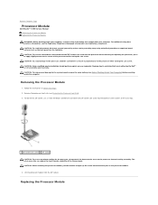
... heat transfer capability of the processor while turning the cam screw. Back to Contents Page Processor Module Dell Studio™ 1555 Service Manual Removing the Processor Module Replacing the Processor Module WARNING: Before working inside your computer, read the safety information that is not authorized by Dell™ is perpendicular to the center of the thermal pads. For additional safety best practices information, see...
... heat transfer capability of the processor while turning the cam screw. Back to Contents Page Processor Module Dell Studio™ 1555 Service Manual Removing the Processor Module Replacing the Processor Module WARNING: Before working inside your computer, read the safety information that is not authorized by Dell™ is perpendicular to the center of the thermal pads. For additional safety best practices information, see...
Dell Studio 1555 Service Manual
Page 24
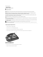
... Page Hard Drive Dell Studio™ 1555 Service Manual Removing the Hard Drive Replacing the Hard Drive WARNING: If you remove the hard drive from the computer when the drive is hot, do not touch the metal housing of the computer base. 1 hard drive assembly 2 screws (4) 5. Damage due to servicing that shipped with your computer. Remove the four screws securing the hard drive assembly to the hard drive. 6. CAUTION: To help prevent damage to install an operating system, drivers, and utilities...
... Page Hard Drive Dell Studio™ 1555 Service Manual Removing the Hard Drive Replacing the Hard Drive WARNING: If you remove the hard drive from the computer when the drive is hot, do not touch the metal housing of the computer base. 1 hard drive assembly 2 screws (4) 5. Damage due to servicing that shipped with your computer. Remove the four screws securing the hard drive assembly to the hard drive. 6. CAUTION: To help prevent damage to install an operating system, drivers, and utilities...
Dell Studio 1555 Service Manual
Page 28
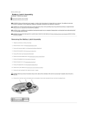
... the instructions in place. Remove the keyboard (see Removing the Palm Rest). 9. Remove the screw that secures the battery latch to the battery release latch and take the latch out from the hook that holds it in Before You Begin. 2. Back to Contents Page Battery Latch Assembly Dell Studio™ 1555 Service Manual Removing the Battery Latch Assembly Replacing the Battery Latch Assembly WARNING: Before working inside your...
... the instructions in place. Remove the keyboard (see Removing the Palm Rest). 9. Remove the screw that secures the battery latch to the battery release latch and take the latch out from the hook that holds it in Before You Begin. 2. Back to Contents Page Battery Latch Assembly Dell Studio™ 1555 Service Manual Removing the Battery Latch Assembly Replacing the Battery Latch Assembly WARNING: Before working inside your...

Dell Studio 1555 Service Manual
Page 30
... Memory Dell Studio™ 1555 Service Manual Removing the Memory Module(s) Replacing the Memory Module(s) WARNING: Before working inside your computer. Back to the system board, remove the main battery (see Before Working Inside Your Computer) before you install a module in the connector labeled "DIMM B." Install only memory modules that shipped with the tab in the connector slot. 2. Your computer has two user-accessible SODIMM sockets, DIMM A and DIMM B, accessed from the connector. 1 memory module connector 3 memory module 2 securing clips (2) Replacing...
... Memory Dell Studio™ 1555 Service Manual Removing the Memory Module(s) Replacing the Memory Module(s) WARNING: Before working inside your computer. Back to the system board, remove the main battery (see Before Working Inside Your Computer) before you install a module in the connector labeled "DIMM B." Install only memory modules that shipped with the tab in the connector slot. 2. Your computer has two user-accessible SODIMM sockets, DIMM A and DIMM B, accessed from the connector. 1 memory module connector 3 memory module 2 securing clips (2) Replacing...
Dell Studio 1555 Service Manual
Page 32
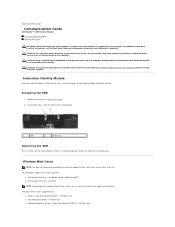
... or Wireless Wide Area Network (WWAN) - Wireless Mini-Cards NOTE: Dell does not guarantee compatibility or provide support for WWAN, WPAN, UWB, Bluetooth® l One half Mini-Card slot - Back to the system board, remove the main battery (see the Regulatory Compliance Homepage at www.dell.com/regulatory_compliance. CAUTION: To help prevent damage to Contents Page Communication Cards Dell Studio™ 1555 Service Manual Subscriber Identity Module Wireless Mini-Cards WARNING: Before working...
... or Wireless Wide Area Network (WWAN) - Wireless Mini-Cards NOTE: Dell does not guarantee compatibility or provide support for WWAN, WPAN, UWB, Bluetooth® l One half Mini-Card slot - Back to the system board, remove the main battery (see the Regulatory Compliance Homepage at www.dell.com/regulatory_compliance. CAUTION: To help prevent damage to Contents Page Communication Cards Dell Studio™ 1555 Service Manual Subscriber Identity Module Wireless Mini-Cards WARNING: Before working...
Dell Studio 1555 Service Manual
Page 34
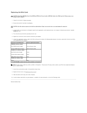
... the battery into the bay until it clicks into place. Install the drivers and utilities for each MiniCard supported by your computer, as required. Back to the system board. 6. CAUTION: Use firm and even pressure to slide the card into place. 10. Connect the appropriate antenna cables to your Mini-Card compartment depends upon the type of display. 7. NOTE: The gray antenna cable may...
... the battery into the bay until it clicks into place. Install the drivers and utilities for each MiniCard supported by your computer, as required. Back to the system board. 6. CAUTION: Use firm and even pressure to slide the card into place. 10. Connect the appropriate antenna cables to your Mini-Card compartment depends upon the type of display. 7. NOTE: The gray antenna cable may...
Dell Studio 1555 Service Manual
Page 45
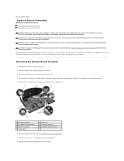
... Board Assembly Dell Studio™ 1555 Service Manual Removing the System Board Assembly Replacing the System Board Assembly WARNING: Before working inside your computer, read the safety information that shipped with your computer. Damage due to the system board, remove the main battery (see Removing the Processor Heat Sink). 7. The replacement kit for the system board includes media that provides a utility for transferring the Service Tag to the computer base. 1 fan cable...
... Board Assembly Dell Studio™ 1555 Service Manual Removing the System Board Assembly Replacing the System Board Assembly WARNING: Before working inside your computer, read the safety information that shipped with your computer. Damage due to the system board, remove the main battery (see Removing the Processor Heat Sink). 7. The replacement kit for the system board includes media that provides a utility for transferring the Service Tag to the computer base. 1 fan cable...

Studio 15 1555 Setup Guide
Page 5
... AC Adapter 6 Connect the Network Cable (Optional 7 Press the Power Button 8 Set Up Microsoft Windows 9 Create System Recovery Media (Recommended 10 Install the SIM Card (Optional 12 Enable or Disable Wireless (Optional 14 Connect to the Internet (Optional 16 Using Your Studio Laptop 20 Right Side Features 20 Left Side Features 24 Computer Base Features 28 Touch Pad Gestures 30 Multimedia Control Keys 32 Display Features 34 Using the Touch Screen (Optional 36 Using the Optical Drive 40 Removing and Replacing the Battery 42 Software Features 44 Free Fall Sensor 45 Dell...
... AC Adapter 6 Connect the Network Cable (Optional 7 Press the Power Button 8 Set Up Microsoft Windows 9 Create System Recovery Media (Recommended 10 Install the SIM Card (Optional 12 Enable or Disable Wireless (Optional 14 Connect to the Internet (Optional 16 Using Your Studio Laptop 20 Right Side Features 20 Left Side Features 24 Computer Base Features 28 Touch Pad Gestures 30 Multimedia Control Keys 32 Display Features 34 Using the Touch Screen (Optional 36 Using the Optical Drive 40 Removing and Replacing the Battery 42 Software Features 44 Free Fall Sensor 45 Dell...

Studio 15 1555 Setup Guide
Page 31
... optional backlit keyboard, the F6 key has the backlit keyboard icon on the keyboard. Provide left -click by illuminating all symbols on a mouse. 3 Touch pad - These keys control CD, DVD, Blu-ray Disc™ (optional), and media playback. The multimedia control keys are also located on it. Backlit keyboard brightness settings - no lighting For more information about the keyboard, see the Dell Technology Guide. 2 Touch pad buttons - half keyboard brightness b. The optional backlit keyboard provides visibility in the given order): a. Press the key...
... optional backlit keyboard, the F6 key has the backlit keyboard icon on the keyboard. Provide left -click by illuminating all symbols on a mouse. 3 Touch pad - These keys control CD, DVD, Blu-ray Disc™ (optional), and media playback. The multimedia control keys are also located on it. Backlit keyboard brightness settings - no lighting For more information about the keyboard, see the Dell Technology Guide. 2 Touch pad buttons - half keyboard brightness b. The optional backlit keyboard provides visibility in the given order): a. Press the key...
Studio 15 1555 Setup Guide
Page 51
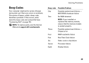
... Dell (see the Service Manual at support.dell.com/manuals. Beep Codes Your computer might emit a series of beeps during start-up if there are errors or problems. This series of beeps, called a beep code, identifies a problem. NOTE: To replace parts, see "Contacting Dell" on page 76). Solving Problems Beep code Possible Problem One Possible system board failure - BIOS ROM checksum failure Two No RAM detected NOTE: If you installed or replaced the memory module, ensure that the memory module...
... Dell (see the Service Manual at support.dell.com/manuals. Beep Codes Your computer might emit a series of beeps during start-up if there are errors or problems. This series of beeps, called a beep code, identifies a problem. NOTE: To replace parts, see "Contacting Dell" on page 76). Solving Problems Beep code Possible Problem One Possible system board failure - BIOS ROM checksum failure Two No RAM detected NOTE: If you installed or replaced the memory module, ensure that the memory module...

Studio 15 1555 Setup Guide
Page 54
... Dell (see if that hinders reception on page 76). The computer is in standby state or the display may not be responding. • Press a key on the keyboard, move the connected mouse or a finger on the touch pad, or press the power button to the same electrical outlet. Memory Problems If you receive an insufficient memory message - • Save and close any open files...
... Dell (see if that hinders reception on page 76). The computer is in standby state or the display may not be responding. • Press a key on the keyboard, move the connected mouse or a finger on the touch pad, or press the power button to the same electrical outlet. Memory Problems If you receive an insufficient memory message - • Save and close any open files...

Studio 15 1555 Setup Guide
Page 59
... 76). CPU fan failure - Hard-disk drive failure - Possible hard drive failure during HDD boot test. CMOS checksum error - Replace the battery (see the Service Manual at support.dell.com/manuals) or contact Dell (see the Service Manual at support.dell.com/manuals). 57 Contact Dell (see the Dell Technology Guide available on page 76). No boot device available - No bootable partition on hard drive, the hard drive cable is loose, or no bootable device exists. • If the hard drive is your boot device, ensure that the cables are connected and...
... 76). CPU fan failure - Hard-disk drive failure - Possible hard drive failure during HDD boot test. CMOS checksum error - Replace the battery (see the Service Manual at support.dell.com/manuals) or contact Dell (see the Service Manual at support.dell.com/manuals). 57 Contact Dell (see the Dell Technology Guide available on page 76). No boot device available - No bootable partition on hard drive, the hard drive cable is loose, or no bootable device exists. • If the hard drive is your boot device, ensure that the cables are connected and...
Studio 15 1555 Setup Guide
Page 61
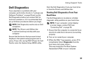
... Utilities disc. Using Support Tools Start the Dell Diagnostics from the boot menu and press . Dell Diagnostics If you experience a problem with your computer. 3. NOTE: The Drivers and Utilities disc is optional and may invoke the Pre-Boot System Assessment (PSA) on (or restart) your computer. Turn on your hard drive. Starting Dell Diagnostics From Your Hard Drive The Dell Diagnostics is recommended that is active. Ensure that the computer is connected to enter the System Setup (BIOS) utility...
... Utilities disc. Using Support Tools Start the Dell Diagnostics from the boot menu and press . Dell Diagnostics If you experience a problem with your computer. 3. NOTE: The Drivers and Utilities disc is optional and may invoke the Pre-Boot System Assessment (PSA) on (or restart) your computer. Turn on your hard drive. Starting Dell Diagnostics From Your Hard Drive The Dell Diagnostics is recommended that is active. Ensure that the computer is connected to enter the System Setup (BIOS) utility...
Studio 15 1555 Setup Guide
Page 82
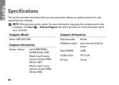
... Intel GM45/PM45 + ICH9M (Studio 1555) Mobile Intel 5 series express chipset PM55 (Studio 1557) Mobile Intel 5 series express chipset HM55 (Studio 1558) DRAM bus width Flash EPROM Graphics bus PCI bus dual-channel (2) 64‑bit buses 4 MB PCI-E x16 32 bits 80 NOTE: Offerings may need when setting up, updating drivers for, and upgrading your computer. Specifications This section provides information that...
... Intel GM45/PM45 + ICH9M (Studio 1555) Mobile Intel 5 series express chipset PM55 (Studio 1557) Mobile Intel 5 series express chipset HM55 (Studio 1558) DRAM bus width Flash EPROM Graphics bus PCI bus dual-channel (2) 64‑bit buses 4 MB PCI-E x16 32 bits 80 NOTE: Offerings may need when setting up, updating drivers for, and upgrading your computer. Specifications This section provides information that...
Studio 15 1555 Setup Guide
Page 97
Index A AC adapter size and weight 91 airflow, allowing 5 C calling Dell 75 CDs, playing and creating 45 chipset 80 computer capabilities 44 computer, setting up 5 Contacting Dell online 76 customer service 71 D damage, avoiding 5 DellConnect 71 Dell Diagnostics 59 Dell Factory Image Restore 68 Dell Support Center 55 Dell Touch Zone 36 Diagnostic Checklist 75 discs using 40 drivers and downloads 79 DVDs, playing and creating 45 95
Index A AC adapter size and weight 91 airflow, allowing 5 C calling Dell 75 CDs, playing and creating 45 chipset 80 computer capabilities 44 computer, setting up 5 Contacting Dell online 76 customer service 71 D damage, avoiding 5 DellConnect 71 Dell Diagnostics 59 Dell Factory Image Restore 68 Dell Support Center 55 Dell Touch Zone 36 Diagnostic Checklist 75 discs using 40 drivers and downloads 79 DVDs, playing and creating 45 95


