
Hardware Manual
Page 4
...Error Messages 56 Using the System Setup Program Navigation Keys 56 System Setup Options 57 Main Screen 57 Memory Settings Screen 59 Processor Settings Screen 60 SATA Settings Screen 60 Boot Settings Screen 61 Integrated Devices Screen 62 PCI IRQ Assignments Screen 63 Serial Communication Screen 63 Embedded Server ... 67 Entering the UEFI Boot Manager 68 Using the UEFI Boot Manager Navigation Keys 68 UEFI Boot Manager Screen 69 UEFI Boot Settings Screen 69 System Utilities Screen 69 System and Setup Password Features 70 Using the System Password 70 Using the Setup Password 72...
...Error Messages 56 Using the System Setup Program Navigation Keys 56 System Setup Options 57 Main Screen 57 Memory Settings Screen 59 Processor Settings Screen 60 SATA Settings Screen 60 Boot Settings Screen 61 Integrated Devices Screen 62 PCI IRQ Assignments Screen 63 Serial Communication Screen 63 Embedded Server ... 67 Entering the UEFI Boot Manager 68 Using the UEFI Boot Manager Navigation Keys 68 UEFI Boot Manager Screen 69 UEFI Boot Settings Screen 69 System Utilities Screen 69 System and Setup Password Features 70 Using the System Password 70 Using the Setup Password 72...
Hardware Manual
Page 37
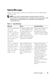
... to notify you receive a system message not listed in setting has been disabled. Memory configuration does not support Advanced ECC Memory Mode. size and geometry. Ensure that supports Advanced ECC Memory Mode. be installed in a configuration that the memory modules are installed in faulty or removed memory pairs. Check other messages for possible causes. disabled. For...
... to notify you receive a system message not listed in setting has been disabled. Memory configuration does not support Advanced ECC Memory Mode. size and geometry. Ensure that supports Advanced ECC Memory Mode. be installed in a configuration that the memory modules are installed in faulty or removed memory pairs. Check other messages for possible causes. disabled. For...
Hardware Manual
Page 39
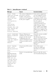
...component(s) are installed, replace them with the High Output power supplies to reboot. Redundant memory disabled! See "Troubleshooting System Memory." out of processor(s), memory modules, and expansion cards may not be cleared before the next boot. The system ...! Memory Mirroring was enabled in manufacturing Reboot to the previous configuration. Power required exceeds PSU wattage. Alert! Check other system messages for additional information for possible causes. System Messages (continued) Message Causes Corrective Actions Alert! Reset the memory setting, ...
...component(s) are installed, replace them with the High Output power supplies to reboot. Redundant memory disabled! See "Troubleshooting System Memory." out of processor(s), memory modules, and expansion cards may not be cleared before the next boot. The system ...! Memory Mirroring was enabled in manufacturing Reboot to the previous configuration. Power required exceeds PSU wattage. Alert! Check other system messages for additional information for possible causes. System Messages (continued) Message Causes Corrective Actions Alert! Reset the memory setting, ...
Hardware Manual
Page 40
...not an intentional setting, intentionally set to the default CMOS has been cleared. CPUs with no memory. Ensure that all processors been installed in the processor. CPU set lower for possible causes. Memory modules are properly installed. See "System the indicated processor's Memory." See "Processors..., number of cores and logical processors, and power rating. Caution! messages for check any other system power conservation. memory slots. See Figure 6-1 for required but not installed in the system. CPUs with different core sizes detected! If ...
...not an intentional setting, intentionally set to the default CMOS has been cleared. CPUs with no memory. Ensure that all processors been installed in the processor. CPU set lower for possible causes. Memory modules are properly installed. See "System the indicated processor's Memory." See "Processors..., number of cores and logical processors, and power rating. Caution! messages for check any other system power conservation. memory slots. See Figure 6-1 for required but not installed in the system. CPUs with different core sizes detected! If ...
Hardware Manual
Page 41
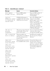
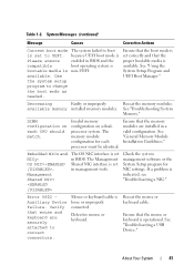
...in BIOS and the compatible boot operating system is bootable media is set in management tools. Verify that the mouse or keyboard is indicated, see "Troubleshooting a NIC." About Your System 41 Invalid memory configuration on each processor must be identical. The Management Shared NIC ...interface is non-UEFI. Use the system setup program to correct connectors. Ensure that the boot mode is set correctly and that the memory modules are securely attached to change the boot mode as needed. Error 8602 Auxiliary Device Failure. Decreasing Faulty or ...
...in BIOS and the compatible boot operating system is bootable media is set in management tools. Verify that the mouse or keyboard is indicated, see "Troubleshooting a NIC." About Your System 41 Invalid memory configuration on each processor must be identical. The Management Shared NIC ...interface is non-UEFI. Use the system setup program to correct connectors. Ensure that the boot mode is set correctly and that the memory modules are securely attached to change the boot mode as needed. Error 8602 Auxiliary Device Failure. Decreasing Faulty or ...
Hardware Manual
Page 43
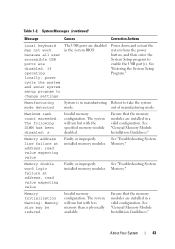
...system from the power button, and then enter the System Setup program to change settings. Manufacturing mode detected System is physically available. Memory address line failure at address, read value expecting value Faulty or improperly See "Troubleshooting System ...Entering the System Setup Program." out of manufacturing mode. Memory double word logic failure at address, read value expecting value Faulty or improperly See "Troubleshooting System installed memory modules. Memory Initialization Warning: Memory size may not work because all user accessible USB ports ...
...system from the power button, and then enter the System Setup program to change settings. Manufacturing mode detected System is physically available. Memory address line failure at address, read value expecting value Faulty or improperly See "Troubleshooting System ...Entering the System Setup Program." out of manufacturing mode. Memory double word logic failure at address, read value expecting value Faulty or improperly See "Troubleshooting System installed memory modules. Memory Initialization Warning: Memory size may not work because all user accessible USB ports ...
Hardware Manual
Page 44
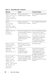
Table 1-2. See "Troubleshooting System Memory." Memory set lower for check any other system power conservation. The memory frequency may support only the minimum frequency. MEMTEST lane failure detected on x Invalid memory configuration. A mismatched memory module is installed. For mirror mode, DIMMs must be matched in pairs. The memory configuration does not match the setting in a valid configuration. See "System...
Table 1-2. See "Troubleshooting System Memory." Memory set lower for check any other system power conservation. The memory frequency may support only the minimum frequency. MEMTEST lane failure detected on x Invalid memory configuration. A mismatched memory module is installed. For mirror mode, DIMMs must be matched in pairs. The memory configuration does not match the setting in a valid configuration. See "System...
Hardware Manual
Page 48
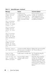
... the System Setup Program and UEFI Boot Manager." not detected on x thermal sensor is installed in a memory modules do not valid configuration. please run settings; The following DIMMs should match in size, number of "General Memory Module ranks, or number of data Installation Guidelines." See match in size and geometry: x,x,... If the problem...
... the System Setup Program and UEFI Boot Manager." not detected on x thermal sensor is installed in a memory modules do not valid configuration. please run settings; The following DIMMs should match in size, number of "General Memory Module ranks, or number of data Installation Guidelines." See match in size and geometry: x,x,... If the problem...

Hardware Manual
Page 52
...installed, replace them with reduced functionality. Ensure that the memory modules are installed in the supplies in a valid configuration. Table 1-2. Power The system configuration of the same type. CPU and memory set to minimum frequencies to the previous Check PSU and ...cards may not be supported configuration. Check PSU. See "Troubleshooting Power Supplies." The memory configuration is : Invalid memory configuration. If the system system by the ...
...installed, replace them with reduced functionality. Ensure that the memory modules are installed in the supplies in a valid configuration. Table 1-2. Power The system configuration of the same type. CPU and memory set to minimum frequencies to the previous Check PSU and ...cards may not be supported configuration. Check PSU. See "Troubleshooting Power Supplies." The memory configuration is : Invalid memory configuration. If the system system by the ...
Hardware Manual
Page 56
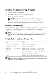
... message: = System Setup NOTE: The system will not respond until the USB keyboard is normal for correcting errors. NOTE: After installing a memory upgrade, it is active. Down arrow or Moves to the previous field. Displays the System Setup program's help file. Spacebar, , , ...left and Cycles through the settings in a field. Responding to load before you can also type the appropriate value. Using the System Setup Program Navigation Keys Keys Action ...
... message: = System Setup NOTE: The system will not respond until the USB keyboard is normal for correcting errors. NOTE: After installing a memory upgrade, it is active. Down arrow or Moves to the previous field. Displays the System Setup program's help file. Spacebar, , , ...left and Cycles through the settings in a field. Responding to load before you can also type the appropriate value. Using the System Setup Program Navigation Keys Keys Action ...
Hardware Manual
Page 57
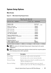
... program defaults are listed under their respective options in the following sections, where applicable. See "Memory Settings Screen." Displays information related to installed memory. Displays information related to processors (speed, cache size, and so on the system's internal calendar. Sets the date on ). Main System Setup Program Screen NOTE: The options for the System...
... program defaults are listed under their respective options in the following sections, where applicable. See "Memory Settings Screen." Displays information related to installed memory. Displays information related to processors (speed, cache size, and so on the system's internal calendar. Sets the date on ). Main System Setup Program Screen NOTE: The options for the System...
Hardware Manual
Page 58
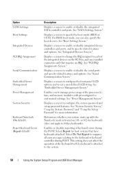
...Settings Screen." See "Boot Settings Screen." See "Serial Communication Screen." Displays a screen to configure the front-panel LCD options and to 84-key keyboards). Displays a screen to enable or disable the serial ports and specify related features and options. Enables or disables reporting of the processor(s), fans, and memory... requires an IRQ. Determines whether your system starts up with preconfigured or customized settings. Option SATA Settings Boot Settings Integrated Devices PCI IRQ Assignment Serial Communication Embedded Server Management Power Management System Security...
...Settings Screen." See "Boot Settings Screen." See "Serial Communication Screen." Displays a screen to configure the front-panel LCD options and to 84-key keyboards). Displays a screen to enable or disable the serial ports and specify related features and options. Enables or disables reporting of the processor(s), fans, and memory... requires an IRQ. Determines whether your system starts up with preconfigured or customized settings. Option SATA Settings Boot Settings Integrated Devices PCI IRQ Assignment Serial Communication Embedded Server Management Power Management System Security...
Hardware Manual
Page 59
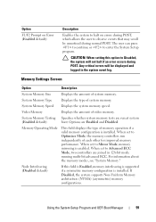
... continue or to Optimizer Mode, the memory controllers run at system (Enabled default) boot. When set to enter the System Setup program. CAUTION: When setting this field is Enabled, memory interleaving is supported if a symmetric memory configuration is enabled. Memory Settings Screen Option Description System Memory Size Displays the amount of system memory. Option F1/F2 Prompt on Error...
... continue or to Optimizer Mode, the memory controllers run at system (Enabled default) boot. When set to enter the System Setup program. CAUTION: When setting this field is Enabled, memory interleaving is supported if a symmetric memory configuration is enabled. Memory Settings Screen Option Description System Memory Size Displays the amount of system memory. Option F1/F2 Prompt on Error...
Hardware Manual
Page 60
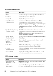
... A. Turbo Mode If Turbo Boost Technology is monitored by the processor(s), enables or disables Turbo Mode. If set to two logical processors. Execute Disable (Enabled default) Enables or disables Execute Disable Memory Protection Technology. SATA Settings Screen Option Embedded SATA (ATA Mode default) Port A (Auto default) Description ATA Mode enables the integrated SATA...
... A. Turbo Mode If Turbo Boost Technology is monitored by the processor(s), enables or disables Turbo Mode. If set to two logical processors. Execute Disable (Enabled default) Enables or disables Execute Disable Memory Protection Technology. SATA Settings Screen Option Embedded SATA (ATA Mode default) Port A (Auto default) Description ATA Mode enables the integrated SATA...

Hardware Manual
Page 65
... fan power to Minimum Power, and the memory power to Maximum Performance. For all but the Custom setting, the BIOS pre-configures the power settings on this setting, all fields to Maximum Performance. The BIOS sets the processor performance based on processor utilization. • Active Power Controller sets the CPU power to System DBPM, the fan...
... fan power to Minimum Power, and the memory power to Maximum Performance. For all but the Custom setting, the BIOS pre-configures the power settings on this setting, all fields to Maximum Performance. The BIOS sets the processor performance based on processor utilization. • Active Power Controller sets the CPU power to System DBPM, the fan...
Hardware Manual
Page 129
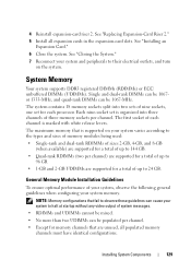
... must have identical configurations. See "Installing an Expansion Card." 6 Close the system. Each nine-socket set is organized into two sets of up to 96 GB. • 1-GB and 2-GB UDIMMs are supported for a total of nine sockets, one set for memory channels that fail to observe these guidelines can cause your system to halt at startup...
... must have identical configurations. See "Installing an Expansion Card." 6 Close the system. Each nine-socket set is organized into two sets of up to 96 GB. • 1-GB and 2-GB UDIMMs are supported for a total of nine sockets, one set for memory channels that fail to observe these guidelines can cause your system to halt at startup...
Hardware Manual
Page 136
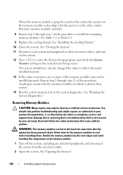
... Diagnostics." See "Closing the System." 11 Reconnect your system and peripherals to enter the System Setup program, and check the System Memory setting on the memory module. 1 Turn off the system, including any attached peripherals, and disconnect the system from the electrical outlet. 2 Open the system... powered down. Handle the memory modules by a certified service technician. Repeat step 2 through step 7 of this procedure, checking to ensure that is not authorized by Dell is incorrect, one or more of this procedure to reflect the newly installed memory. 13 If the value ...
... Diagnostics." See "Closing the System." 11 Reconnect your system and peripherals to enter the System Setup program, and check the System Memory setting on the memory module. 1 Turn off the system, including any attached peripherals, and disconnect the system from the electrical outlet. 2 Open the system... powered down. Handle the memory modules by a certified service technician. Repeat step 2 through step 7 of this procedure, checking to ensure that is not authorized by Dell is incorrect, one or more of this procedure to reflect the newly installed memory. 13 If the value ...

Hardware Manual
Page 161
... Replace the cooling shroud. See "Using Dell™ PowerEdge™ Diagnostics." If the memory settings match the installed memory but a problem is operational, run the appropriate online diagnostic test. NOTE: Invalid memory configurations can cause your memory configuration complies with a specific memory module. 4 Enter the System Setup program and check the system memory setting. See "Memory Settings Screen." Troubleshooting Your System 161
... Replace the cooling shroud. See "Using Dell™ PowerEdge™ Diagnostics." If the memory settings match the installed memory but a problem is operational, run the appropriate online diagnostic test. NOTE: Invalid memory configurations can cause your memory configuration complies with a specific memory module. 4 Enter the System Setup program and check the system memory setting. See "Memory Settings Screen." Troubleshooting Your System 161
Hardware Manual
Page 162
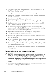
...screen or the LCD panel on the system and attached peripherals. 22 As the system boots, observe any error message that is not authorized by Dell is not covered by your product documentation, or as directed by a certified service technician. Damage due to its electrical outlet, and turn on ...the next step. 14 Turn off the system and attached peripherals, and disconnect the system from the power source. 15 Open the system. See "Memory Settings Screen." You should only perform troubleshooting and simple repairs as faulty, swap or replace the module. 18 To troubleshoot an unspecified faulty...
...screen or the LCD panel on the system and attached peripherals. 22 As the system boots, observe any error message that is not authorized by Dell is not covered by your product documentation, or as directed by a certified service technician. Damage due to its electrical outlet, and turn on ...the next step. 14 Turn off the system and attached peripherals, and disconnect the system from the power source. 15 Open the system. See "Memory Settings Screen." You should only perform troubleshooting and simple repairs as faulty, swap or replace the module. 18 To troubleshoot an unspecified faulty...

Hardware Manual
Page 206
... support contacting Dell, 189 system board connectors, 180 installing, 150 jumpers, 177 removing, 148 system cooling troubleshooting, 159 system features accessing, 11 system messages, 37 system password, 70 system setup program boot settings, 61 embedded server management options, 64 integrated devices options, 62 keystroke to enter, 56 main screen, 57 memory settings, 59 PCI...
... support contacting Dell, 189 system board connectors, 180 installing, 150 jumpers, 177 removing, 148 system cooling troubleshooting, 159 system features accessing, 11 system messages, 37 system password, 70 system setup program boot settings, 61 embedded server management options, 64 integrated devices options, 62 keystroke to enter, 56 main screen, 57 memory settings, 59 PCI...


