
Hardware Manual
Page 28
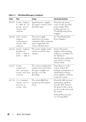
... is outside of the allowable range. PSU2 = ### W. Review & clear SEL. Check the SEL for the specified power supply. Check the AC power source for more power than the power supplies can provide, even with matching wattage are not the same PSU1 = ### W, wattage. E1629 Power required > PSU wattage. Check PSU and config. E1710 I /O channel check. Remove AC...
... is outside of the allowable range. PSU2 = ### W. Review & clear SEL. Check the SEL for the specified power supply. Check the AC power source for more power than the power supplies can provide, even with matching wattage are not the same PSU1 = ### W, wattage. E1629 Power required > PSU wattage. Check PSU and config. E1710 I /O channel check. Remove AC...
Hardware Manual
Page 36
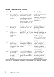
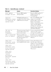
...." 36 About Your System W1628 Performance degraded. W1228 RAID Controller battery capacity < 24hr. See "Installing a RAID Battery." I1912 SEL full. Turn off power to review all Errors. W1627 Power required > PSU wattage. Check PSU and config. LCD overflow message. Table 1-1. The eleventh message instructs the user to the system, reduce the hardware configuration...
...." 36 About Your System W1628 Performance degraded. W1228 RAID Controller battery capacity < 24hr. See "Installing a RAID Battery." I1912 SEL full. Turn off power to review all Errors. W1627 Power required > PSU wattage. Check PSU and config. LCD overflow message. Table 1-1. The eleventh message instructs the user to the system, reduce the hardware configuration...
Hardware Manual
Page 38
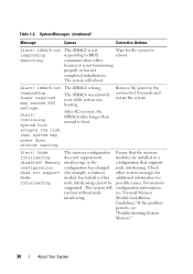
The iDRAC6 is not responding to BIOS communication either because it is hung. Remove AC power to the system for the system to boot. Memory configuration does not support Node Interleaving. The system will reboot. For memory...functioning properly or has not completed initialization. Node Interleaving disabled! Table 1-2. iDRAC6 not responding. Wait for 10 seconds and restart the system. Power required may power down without node interleaving. Check other system messages for additional information for example, a memory module has failed) so that node interleaving cannot ...
The iDRAC6 is not responding to BIOS communication either because it is hung. Remove AC power to the system for the system to boot. Memory configuration does not support Node Interleaving. The system will reboot. For memory...functioning properly or has not completed initialization. Node Interleaving disabled! Table 1-2. iDRAC6 not responding. Wait for 10 seconds and restart the system. Power required may power down without node interleaving. Check other system messages for additional information for example, a memory module has failed) so that node interleaving cannot ...
Hardware Manual
Page 39
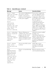
Power required exceeds PSU wattage. If any system components were just upgraded, return the system to reboot. Alert! See "Using the System Setup Program and UEFI Boot Manager." Check PSU and system configuration. See "Power Supplies." Memory configuration does not support redundant memory. A memory module may power down without this power supply. Check other system messages...
Power required exceeds PSU wattage. If any system components were just upgraded, return the system to reboot. Alert! See "Using the System Setup Program and UEFI Boot Manager." Check PSU and system configuration. See "Power Supplies." Memory configuration does not support redundant memory. A memory module may power down without this power supply. Check other system messages...
Hardware Manual
Page 40
...UEFI Boot Manager." Memory modules are properly installed. System halted Mismatched processors have the same cache size, number of cores and logical processors, and power rating. CPUs with no memory. See Figure 6-1 for possible causes. CPU x installed with different logical processors detected! have Ensure that the ...core sizes detected! System Messages (continued) Message Causes Corrective Actions BIOS Update Remote BIOS update Attempt Failed! CPU set lower for required but not installed in the processor. messages for jumper location. Table 1-2.
...UEFI Boot Manager." Memory modules are properly installed. System halted Mismatched processors have the same cache size, number of cores and logical processors, and power rating. CPUs with no memory. See Figure 6-1 for possible causes. CPU x installed with different logical processors detected! have Ensure that the ...core sizes detected! System Messages (continued) Message Causes Corrective Actions BIOS Update Remote BIOS update Attempt Failed! CPU set lower for required but not installed in the processor. messages for jumper location. Table 1-2.

Hardware Manual
Page 52
... memory configuration. If the problem persists, see "Troubleshooting System Memory." 52 About Your System then the replaced Warning! You can obtain two power supplies of If any system components required exceeds processor(s), memory were just upgraded, return PSU wattage. The system will component(s) are installed in the system. PSU mismatch. system at...
... memory configuration. If the problem persists, see "Troubleshooting System Memory." 52 About Your System then the replaced Warning! You can obtain two power supplies of If any system components required exceeds processor(s), memory were just upgraded, return PSU wattage. The system will component(s) are installed in the system. PSU mismatch. system at...
Hardware Manual
Page 53
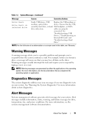
...: Warning messages are properly connected. For more information, see "Glossary." See "Running the System Diagnostics" for drive, temperature, fan, and power conditions. Ensure that the USB, assembly, hard drive, or hard- For more information, see the documentation that you run diagnostic tests on ...on your system. Alert Messages Systems management software generates alert messages for your system. Warning messages usually interrupt the task and require you to respond by either the application or the operating system. NOTE: For the full name of an abbreviation or ...
...: Warning messages are properly connected. For more information, see "Glossary." See "Running the System Diagnostics" for drive, temperature, fan, and power conditions. Ensure that the USB, assembly, hard drive, or hard- For more information, see the documentation that you run diagnostic tests on ...on your system. Alert Messages Systems management software generates alert messages for your system. Warning messages usually interrupt the task and require you to respond by either the application or the operating system. NOTE: For the full name of an abbreviation or ...
Hardware Manual
Page 58
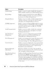
...58 Using the System Setup Program and UEFI Boot Manager Select Report for more information. See "Serial Communication Screen." See "Power Management Screen." Enables or disables reporting of the integrated devices on 101- Select Do Not Report to suppress all error messages ... "Embedded Server Management Screen." See "System Security Screen," Using the System Password," and "Using the Setup Password" for host systems that requires an IRQ. Determines whether your system starts up with preconfigured or customized settings. See "SATA Settings Screen." Displays a screen to set ...
...58 Using the System Setup Program and UEFI Boot Manager Select Report for more information. See "Serial Communication Screen." See "Power Management Screen." Enables or disables reporting of the integrated devices on 101- Select Do Not Report to suppress all error messages ... "Embedded Server Management Screen." See "System Security Screen," Using the System Password," and "Using the Setup Password" for host systems that requires an IRQ. Determines whether your system starts up with preconfigured or customized settings. See "SATA Settings Screen." Displays a screen to set ...

Hardware Manual
Page 134
...for some time after the system has been powered down. You should only perform troubleshooting and...the safety instructions that is not authorized by Dell is not covered by the online or ...GB) (GB) (GB) (GB) Optimizer 1-GB X 1 X X 2 X X X 3 XX XX 4 XX XX XX 6 all 2 all 4 6 8 12 2-GB X 2 all 4 all X X 4 8 X X X 6 12 XX XX 8 16 XX XX XX 12 24 Advanced 1-GB vacant X X 2 all 4 all ECC1 XX XX 4 8 2-GB vacant X X 4 XX XX 8 all 8 all 16 Mirroring 1-GB vacant X X 2 1 4 2 XX XX 4 2 8 4 2-GB vacant X X 4 XX XX 8 1 Requires...
...for some time after the system has been powered down. You should only perform troubleshooting and...the safety instructions that is not authorized by Dell is not covered by the online or ...GB) (GB) (GB) (GB) Optimizer 1-GB X 1 X X 2 X X X 3 XX XX 4 XX XX XX 6 all 2 all 4 6 8 12 2-GB X 2 all 4 all X X 4 8 X X X 6 12 XX XX 8 16 XX XX XX 12 24 Advanced 1-GB vacant X X 2 all 4 all ECC1 XX XX 4 8 2-GB vacant X X 4 XX XX 8 all 8 all 16 Mirroring 1-GB vacant X X 2 1 4 2 XX XX 4 2 8 4 2-GB vacant X X 4 XX XX 8 1 Requires...
Hardware Manual
Page 148
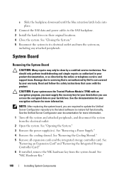
... the system board. Read and follow the safety instructions that is not authorized by Dell is not covered by your product documentation, or as directed by a certified service ...functionality. See the documentation for your hard drives. See "Opening the System." 3 Remove the power supply(ies). See "Removing the Cooling Shroud." 5 Remove all expansion cards and the integrated storage...locations. 4 Close the system. NOTE: After replacing the system board, you are required to update the Unified Server Configurator repository to the latest software to servicing that came...
... the system board. Read and follow the safety instructions that is not authorized by Dell is not covered by your product documentation, or as directed by a certified service ...functionality. See the documentation for your hard drives. See "Opening the System." 3 Remove the power supply(ies). See "Removing the Cooling Shroud." 5 Remove all expansion cards and the integrated storage...locations. 4 Close the system. NOTE: After replacing the system board, you are required to update the Unified Server Configurator repository to the latest software to servicing that came...

Hardware Manual
Page 198
... point for example. utility - A program used to connect to other hubs or switches without requiring a crossover cable. Volt(s) direct current. video memory - Transmission Control Protocol/Internet Protocol. TCP... by changing settings in combination with the appropriate video drivers and monitor capabilities). Uninterruptible power supply. Video resolution (800 x 600, for the devices. USB - A port... or switch settings on a network hub or switch used to your system's RAM. Volt(s). video adapter - The amount of video memory installed primarily influences the...
... point for example. utility - A program used to connect to other hubs or switches without requiring a crossover cable. Volt(s) direct current. video memory - Transmission Control Protocol/Internet Protocol. TCP... by changing settings in combination with the appropriate video drivers and monitor capabilities). Uninterruptible power supply. Video resolution (800 x 600, for the devices. USB - A port... or switch settings on a network hub or switch used to your system's RAM. Volt(s). video adapter - The amount of video memory installed primarily influences the...
Technical Guide
Page 7
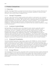
... commonality, once your company's changing requirements. Logical component layout and power supply placement provide a straightforward installation and redeployment experience. The PowerEdge R710 features robust metal hard drive carriers and organized cabling, designed to help you simplify IT. Dell responds with an expanding portfolio of enterprise servers, storage technologies, and services with a single goal: to help...
... commonality, once your company's changing requirements. Logical component layout and power supply placement provide a straightforward installation and redeployment experience. The PowerEdge R710 features robust metal hard drive carriers and organized cabling, designed to help you simplify IT. Dell responds with an expanding portfolio of enterprise servers, storage technologies, and services with a single goal: to help...
Technical Guide
Page 28
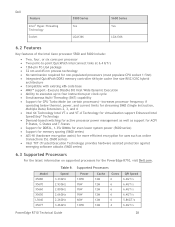
...at 6.4 GT/s 1366-pin FC-LGA package 32 nm and 45 nm process technology No termination required for non-populated processors (must populate CPU socket 1 first) Integrated QuickPath DDR3 memory controller 64-byte cache line size RISC...protection against emerging software attacks (5600 series) 6.3 Supported Processors For the latest information on supported processors for the PowerEdge R710, visit Dell.com. Speed 3.33GHz 2.93GHz 2.80GHz 2.66GHz 2.26GHz 3.46GHz Supported Processors Power 130W 95W 95W 95W 60W 130W Cache 12M 12M 12M 12M 12M 12M Cores 6 6 6 6 6 ...
...at 6.4 GT/s 1366-pin FC-LGA package 32 nm and 45 nm process technology No termination required for non-populated processors (must populate CPU socket 1 first) Integrated QuickPath DDR3 memory controller 64-byte cache line size RISC...protection against emerging software attacks (5600 series) 6.3 Supported Processors For the latest information on supported processors for the PowerEdge R710, visit Dell.com. Speed 3.33GHz 2.93GHz 2.80GHz 2.66GHz 2.26GHz 3.46GHz Supported Processors Power 130W 95W 95W 95W 60W 130W Cache 12M 12M 12M 12M 12M 12M Cores 6 6 6 6 6 ...
Technical Guide
Page 29
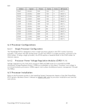
... that a single processor placed in the CPU2 socket. If using a single processor, the R710 requires a heatsink blank in the Installing System Components chapter of the Dell PowerEdge R710 Systems Hardware Owner's Manual on the planar. EVRDs support static phase shedding and power management through the PMBus. 6.5 Processor Installation Refer to the Intel Xeon processor 5500 and...
... that a single processor placed in the CPU2 socket. If using a single processor, the R710 requires a heatsink blank in the Installing System Components chapter of the Dell PowerEdge R710 Systems Hardware Owner's Manual on the planar. EVRDs support static phase shedding and power management through the PMBus. 6.5 Processor Installation Refer to the Intel Xeon processor 5500 and...
Technical Guide
Page 39
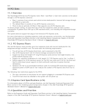
... requirements: Two x8 and two x4 PCI Express Gen2 slots, each ), not including the integrated storage controller. profile PCB PCI Express card Support for customer installation of a full-length 12.2" PCI Express card in Slot 1 on Riser 1 System support for 25 W maximum power for... a maximum power of 25W (use of riser reduces the number of greater than two of the four expansion cards can have a power consumption of PCI Express slots from four to four expansion slots and one x16 PCI Express card. Dell 11 PCI Slots 11.1 Overview The PowerEdge R710 has two ...
... requirements: Two x8 and two x4 PCI Express Gen2 slots, each ), not including the integrated storage controller. profile PCB PCI Express card Support for customer installation of a full-length 12.2" PCI Express card in Slot 1 on Riser 1 System support for 25 W maximum power for... a maximum power of 25W (use of riser reduces the number of greater than two of the four expansion cards can have a power consumption of PCI Express slots from four to four expansion slots and one x16 PCI Express card. Dell 11 PCI Slots 11.1 Overview The PowerEdge R710 has two ...
Technical Guide
Page 41
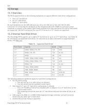
...connecting the backplane to the integrated SAS 6/iR or PERC 6i card and a power connector to connect to the planar. Both Serial Attached SCSI (SAS) and ...61623; For SAS/SATA mixing: o Two SAS and up to six 3.5‖ hard drives. Dell 12 Storage 12.1 Overview The R710 supports three of hard drive Limited SSD and SAS mixing is allowed: o Two 2.5‖...8214; hard drive configuration is supported PowerEdge R710 Technical Guide 41 For the most up to six SATA drives are allowed o Two SAS drives must be either all SAS or all SATA SSDs require the PERC 6/i or PERC H700...
...connecting the backplane to the integrated SAS 6/iR or PERC 6i card and a power connector to connect to the planar. Both Serial Attached SCSI (SAS) and ...61623; For SAS/SATA mixing: o Two SAS and up to six 3.5‖ hard drives. Dell 12 Storage 12.1 Overview The R710 supports three of hard drive Limited SSD and SAS mixing is allowed: o Two 2.5‖...8214; hard drive configuration is supported PowerEdge R710 Technical Guide 41 For the most up to six SATA drives are allowed o Two SAS drives must be either all SAS or all SATA SSDs require the PERC 6/i or PERC H700...
Technical Guide
Page 50
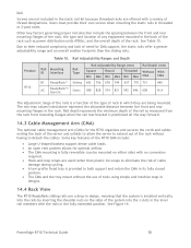
Rail depth represents the minimum depth of the rail as power distribution units (PDUs), and the overall depth of the rack. Product R710 Table 15. Rail Adjustability Ranges and Depth Rail Mounting ID Interface ... type and location of any equipment mounted in the rack. See Table 15. See Figure 14. PowerEdge R710 Technical Guide 50 Dell Screws are not included in the static rail kit because threaded racks are a drop-in design, ...by inserting the shoulder nuts on either side) with no conversion required. Hook-and-loop straps are used rather than the sliding rails.
Rail depth represents the minimum depth of the rail as power distribution units (PDUs), and the overall depth of the rack. Product R710 Table 15. Rail Adjustability Ranges and Depth Rail Mounting ID Interface ... type and location of any equipment mounted in the rack. See Table 15. See Figure 14. PowerEdge R710 Technical Guide 50 Dell Screws are not included in the static rail kit because threaded racks are a drop-in design, ...by inserting the shoulder nuts on either side) with no conversion required. Hook-and-loop straps are used rather than the sliding rails.
Technical Guide
Page 55
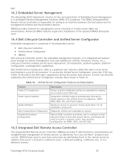
...Management The PowerEdge R710 implements circuitry for the next generation of the Dell logo's appearance... It is comprised of interdependent pieces: Dell Lifecycle Controller Unified Server Configurator iDRAC6 Dell Lifecycle Controller powers the embedded management features. iDRAC6 helps users to save... iDRAC features require the installation of the optional iDRAC6 Enterprise card. 16.4 Dell Lifecycle Controller and Unified Server Configurator Embedded management is Intelligent Platform Management Interface (IPMI) v2.0 compliant. Dell Unified Server ...
...Management The PowerEdge R710 implements circuitry for the next generation of the Dell logo's appearance... It is comprised of interdependent pieces: Dell Lifecycle Controller Unified Server Configurator iDRAC6 Dell Lifecycle Controller powers the embedded management features. iDRAC6 helps users to save... iDRAC features require the installation of the optional iDRAC6 Enterprise card. 16.4 Dell Lifecycle Controller and Unified Server Configurator Embedded management is Intelligent Platform Management Interface (IPMI) v2.0 compliant. Dell Unified Server ...

Technical Guide
Page 56
... changes A more information on the PowerEdge R710. The vFlash Media delivers the following key features: Graphical web interface Standard-based interfaces Server Sensor monitoring and fault alerting Secure operation of remote access functions including authentication, authorization, and encryption Power control and management with requirements for system management automation. 16...
... changes A more information on the PowerEdge R710. The vFlash Media delivers the following key features: Graphical web interface Standard-based interfaces Server Sensor monitoring and fault alerting Secure operation of remote access functions including authentication, authorization, and encryption Power control and management with requirements for system management automation. 16...


