
Hardware Manual
Page 6
... 91 Internal USB Cable 93 Removing the Internal USB Cable 93 Installing the Internal USB Cable 93 Integrated Dell Remote Access Controller 6 (iDRAC6) Enterprise Card (Optional 94 Installing an iDRAC6 Enterprise Card 94 Removing an iDRAC6 Enterprise Card 95 VFlash Media (Optional 96 NIC Hardware Key 97 Cooling Shroud 98 Removing the Cooling Shroud...
... 91 Internal USB Cable 93 Removing the Internal USB Cable 93 Installing the Internal USB Cable 93 Integrated Dell Remote Access Controller 6 (iDRAC6) Enterprise Card (Optional 94 Installing an iDRAC6 Enterprise Card 94 Removing an iDRAC6 Enterprise Card 95 VFlash Media (Optional 96 NIC Hardware Key 97 Cooling Shroud 98 Removing the Cooling Shroud...
Hardware Manual
Page 13
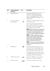
.... NOTE: To force an ungraceful shutdown, press and hold the power button for system information including the Express Service tag, Embedded NIC1 MAC address, and iDRAC6 Enterprise card MAC address. Connects USB devices to the system. Used to troubleshoot software and device driver errors when using certain operating systems. This button...
.... NOTE: To force an ungraceful shutdown, press and hold the power button for system information including the Express Service tag, Embedded NIC1 MAC address, and iDRAC6 Enterprise card MAC address. Connects USB devices to the system. Used to troubleshoot software and device driver errors when using certain operating systems. This button...
Hardware Manual
Page 17
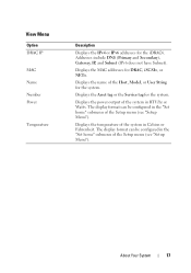
... in BTU/hr or Watts. Displays the temperature of the system in the "Set home" submenu of the Host, Model, or User String for the iDRAC6. View Menu Option DRAC IP MAC Name Number Power Temperature Description Displays the IPv4 or IPv6 addresses for the system. Displays the name of the...
... in BTU/hr or Watts. Displays the temperature of the system in the "Set home" submenu of the Host, Model, or User String for the iDRAC6. View Menu Option DRAC IP MAC Name Number Power Temperature Description Displays the IPv4 or IPv6 addresses for the system. Displays the name of the...
Hardware Manual
Page 20
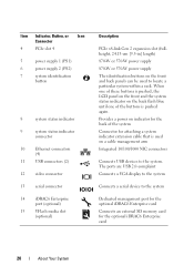
... LCD panel on the front and the system status indicator on the back flash blue until one of the system Connector for the optional iDRAC6 Enterprise card 20 About Your System Item Indicator, Button, or Icon Connector 4 PCIe slot 4 5 power supply 1 (PS1) 6 power... button 8 system status indicator 9 system status indicator connector 10 Ethernet connectors (4) 11 USB connectors (2) 12 video connector 13 serial connector 14 iDRAC6 Enterprise port (optional) 15 VFlash media slot (optional) Description PCIe x8-link Gen 2 expansion slot (fullheight, 24.13-cm [9.5-in] length...
... LCD panel on the front and the system status indicator on the back flash blue until one of the system Connector for the optional iDRAC6 Enterprise card 20 About Your System Item Indicator, Button, or Icon Connector 4 PCIe slot 4 5 power supply 1 (PS1) 6 power... button 8 system status indicator 9 system status indicator connector 10 Ethernet connectors (4) 11 USB connectors (2) 12 video connector 13 serial connector 14 iDRAC6 Enterprise port (optional) 15 VFlash media slot (optional) Description PCIe x8-link Gen 2 expansion slot (fullheight, 24.13-cm [9.5-in] length...
Hardware Manual
Page 38
... the system. Remove AC power to the system for the system to boot. iDRAC6 not responding. The iDRAC6 was remotely reset while system was booting After AC recovery, the iDRAC6 takes longer than normal to reboot. Memory configuration does not support Node Interleaving.... memory configuration information, see "Troubleshooting System Memory." 38 About Your System Power required may power down without node interleaving. The iDRAC6 is not functioning properly or has not completed initialization. The memory configuration does not support node interleaving, or the configuration has ...
... the system. Remove AC power to the system for the system to boot. iDRAC6 not responding. The iDRAC6 was remotely reset while system was booting After AC recovery, the iDRAC6 takes longer than normal to reboot. Memory configuration does not support Node Interleaving.... memory configuration information, see "Troubleshooting System Memory." 38 About Your System Power required may power down without node interleaving. The iDRAC6 is not functioning properly or has not completed initialization. The memory configuration does not support node interleaving, or the configuration has ...

Hardware Manual
Page 50
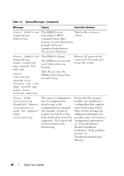
... Corrective Actions Unable to restore full functionality. See "Processors." The following DIMM has been disabled: x Invalid memory configuration. support.dell.com. If the problem persists, see "Getting Help." See "General Memory Module Installation Guidelines." Unsupported DIMM detected. Restart the ...modules are mismatched in a valid configuration. See "General Memory Module Installation Guidelines." 50 About Your System The iDRAC6 Enterprise card Restore the flash memory flash memory may be using the latest version on performing a field replacement of ...
... Corrective Actions Unable to restore full functionality. See "Processors." The following DIMM has been disabled: x Invalid memory configuration. support.dell.com. If the problem persists, see "Getting Help." See "General Memory Module Installation Guidelines." Unsupported DIMM detected. Restart the ...modules are mismatched in a valid configuration. See "General Memory Module Installation Guidelines." 50 About Your System The iDRAC6 Enterprise card Restore the flash memory flash memory may be using the latest version on performing a field replacement of ...
Hardware Manual
Page 73
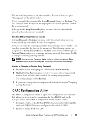
...password. iDRAC Configuration Utility The iDRAC Configuration Utility is a pre-boot configuration environment that allows you to view and set parameters for the iDRAC6 and for the setup password. When you want to Enabled. Operating With a Setup Password Enabled If Setup Password is not required). The...you do not enter the correct password in conjunction with the Setup Password option to : • Configure, enable, or disable the iDRAC6 local area network through the Password Status option, you must enter the correct setup password before modifying most of the System Setup options....
...password. iDRAC Configuration Utility The iDRAC Configuration Utility is a pre-boot configuration environment that allows you to view and set parameters for the iDRAC6 and for the setup password. When you want to Enabled. Operating With a Setup Password Enabled If Setup Password is not required). The...you do not enter the correct password in conjunction with the Setup Password option to : • Configure, enable, or disable the iDRAC6 local area network through the Password Status option, you must enter the correct setup password before modifying most of the System Setup options....
Hardware Manual
Page 74
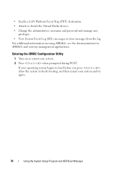
... or restart your system and try again. 74 Using the System Setup Program and UEFI Boot Manager Entering the iDRAC Configuration Utility 1 Turn on using iDRAC6, see the documentation for iDRAC6 and systems management applications.
... or restart your system and try again. 74 Using the System Setup Program and UEFI Boot Manager Entering the iDRAC Configuration Utility 1 Turn on using iDRAC6, see the documentation for iDRAC6 and systems management applications.
Hardware Manual
Page 76
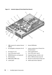
...) 6 5 4 3 2 1 7 8 9 16 15 14 13 12 10 11 1 USB connector for optional internal USB key 3 hot-swappable cooling fans (4 or 5) 5 processors (1 or 2) 7 riser 2 (PCIe slots 3 and 4) 9 iDRAC6 Enterprise card (optional) 11 SAS backplane 13 RAID battery (PERC only) 15 control panel 2 Internal SD Module 4 memory modules (up to 18 total, 9 for each...
...) 6 5 4 3 2 1 7 8 9 16 15 14 13 12 10 11 1 USB connector for optional internal USB key 3 hot-swappable cooling fans (4 or 5) 5 processors (1 or 2) 7 riser 2 (PCIe slots 3 and 4) 9 iDRAC6 Enterprise card (optional) 11 SAS backplane 13 RAID battery (PERC only) 15 control panel 2 Internal SD Module 4 memory modules (up to 18 total, 9 for each...
Hardware Manual
Page 78
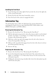
... the tag until it disengages from the slot in "About Your System" for system information including the Express Service tag, Embedded NIC1 MAC address, and iDRAC6 Enterprise card MAC address. Installing the Front Bezel 1 Insert the hinge tab on the right of the bezel into place. 78 Installing System Components Replacing...
... the tag until it disengages from the slot in "About Your System" for system information including the Express Service tag, Embedded NIC1 MAC address, and iDRAC6 Enterprise card MAC address. Installing the Front Bezel 1 Insert the hinge tab on the right of the bezel into place. 78 Installing System Components Replacing...
Hardware Manual
Page 94
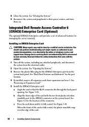
...." 9 Reconnect the system and peripherals to servicing that is not authorized by Dell is not covered by your product documentation, or as authorized in your warranty. Installing an iDRAC6 Enterprise Card CAUTION: Many repairs may only be done by the online or telephone... technician. See "Back Panel Features and Indicators" for managing the server remotely. See Figure 3-10. Integrated Dell Remote Access Controller 6 (iDRAC6) Enterprise Card (Optional) The optional iDRAC6 Enterprise card provides a set of advanced features for the port location. 4 If installed, remove all expansion ...
...." 9 Reconnect the system and peripherals to servicing that is not authorized by Dell is not covered by your product documentation, or as authorized in your warranty. Installing an iDRAC6 Enterprise Card CAUTION: Many repairs may only be done by the online or telephone... technician. See "Back Panel Features and Indicators" for managing the server remotely. See Figure 3-10. Integrated Dell Remote Access Controller 6 (iDRAC6) Enterprise Card (Optional) The optional iDRAC6 Enterprise card provides a set of advanced features for the port location. 4 If installed, remove all expansion ...
Hardware Manual
Page 95
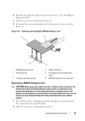
...card 3 VFlash SD card 5 retention standoff posts (2) 2 VFlash media slot 4 RJ-45 Ethernet port (underneath card) 6 iDRAC6 Enterprise card connector Removing an iDRAC6 Enterprise Card CAUTION: Many repairs may only be done by a certified service technician. See "Closing the System." 8 Reconnect the...from the electrical outlet. 2 Open the system. Installing System Components 95 Read and follow the safety instructions that is not authorized by Dell is not covered by your product documentation, or as directed by the online or telephone service and support team. See "Opening the ...
...card 3 VFlash SD card 5 retention standoff posts (2) 2 VFlash media slot 4 RJ-45 Ethernet port (underneath card) 6 iDRAC6 Enterprise card connector Removing an iDRAC6 Enterprise Card CAUTION: Many repairs may only be done by a certified service technician. See "Closing the System." 8 Reconnect the...from the electrical outlet. 2 Open the system. Installing System Components 95 Read and follow the safety instructions that is not authorized by Dell is not covered by your product documentation, or as directed by the online or telephone service and support team. See "Opening the ...
Hardware Manual
Page 96
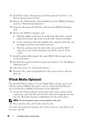
... 7 Install the plastic filler plug for the slot location. To remove the card, push inward on . c Slide the card away from the iDRAC6 Enterprise card. See "Back Panel Features and Indicators" for the vacated RJ-45 Ethernet port in the system back panel. 8 Reinstall the expansion ...Expansion Card." 4 Remove the VFlash media card (if installed) from the back of the SD card (with the optional iDRAC6 Enterprise card. See "Integrated Dell Remote Access Controller 6 (iDRAC6) Enterprise Card (Optional)." 1 Locate the VFlash media slot on the back of the system and insert the contact-pin end...
... 7 Install the plastic filler plug for the slot location. To remove the card, push inward on . c Slide the card away from the iDRAC6 Enterprise card. See "Back Panel Features and Indicators" for the vacated RJ-45 Ethernet port in the system back panel. 8 Reinstall the expansion ...Expansion Card." 4 Remove the VFlash media card (if installed) from the back of the SD card (with the optional iDRAC6 Enterprise card. See "Integrated Dell Remote Access Controller 6 (iDRAC6) Enterprise Card (Optional)." 1 Locate the VFlash media slot on the back of the system and insert the contact-pin end...
Hardware Manual
Page 151
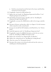
... Bracket." 15 Replace the cooling shroud. Installing System Components 151 See "Installing an Expansion Card." 13 If applicable, transfer the iDRAC6 Enterprise card to its electrical outlet and turn the system on the system board). 11 If removed, reinstall the SAS backplane and...the back of the connectors on , including any attached peripherals. See "Installing the Cooling Shroud." 16 Close the system. See "Installing an iDRAC6 Enterprise Card." 14 Replace the fan bracket. See "Replacing Expansion-Card Riser 1" and "Replacing Expansion-Card Riser 2." 8 Reinstall the integrated ...
... Bracket." 15 Replace the cooling shroud. Installing System Components 151 See "Installing an Expansion Card." 13 If applicable, transfer the iDRAC6 Enterprise card to its electrical outlet and turn the system on the system board). 11 If removed, reinstall the SAS backplane and...the back of the connectors on , including any attached peripherals. See "Installing the Cooling Shroud." 16 Close the system. See "Installing an iDRAC6 Enterprise Card." 14 Replace the fan bracket. See "Replacing Expansion-Card Riser 1" and "Replacing Expansion-Card Riser 2." 8 Reinstall the integrated ...

Hardware Manual
Page 156
...are installed and the protocols are all set to the same data transmission speed and duplex. 4 Ensure that is not authorized by Dell is not covered by your product documentation, or as directed by a certified service technician. See "Opening the System." 3 Disassemble ...NIC hardware key • Internal SD Module • Expansion cards and both expansion-card risers • Integrated storage controller • iDRAC6 Enterprise card 156 Troubleshooting Your System See the NIC's documentation. 5 Enter the System Setup program and confirm that all troubleshooting fails, see "...
...are installed and the protocols are all set to the same data transmission speed and duplex. 4 Ensure that is not authorized by Dell is not covered by your product documentation, or as directed by a certified service technician. See "Opening the System." 3 Disassemble ...NIC hardware key • Internal SD Module • Expansion cards and both expansion-card risers • Integrated storage controller • iDRAC6 Enterprise card 156 Troubleshooting Your System See the NIC's documentation. 5 Enter the System Setup program and confirm that all troubleshooting fails, see "...

Hardware Manual
Page 174
... in the system does not operate properly, component failure may cause invalid results or error messages. 1 As the system boots, press . 2 Select Diagnostics from the iDRAC6 Express System Services menu. This test can use the system diagnostics to exit. When to test only your system. Testing Option Express Test Extended Test...
... in the system does not operate properly, component failure may cause invalid results or error messages. 1 As the system boots, press . 2 Select Diagnostics from the iDRAC6 Express System Services menu. This test can use the system diagnostics to exit. When to test only your system. Testing Option Express Test Extended Test...
Hardware Manual
Page 178
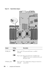
Figure 6-1. NVRAM_CLR Pins 3 and 5 The configuration settings are retained at the next AC power cycle. System Board Jumpers Jumper Setting Description PWRD_EN Pins 2 and 4 The password feature is enabled. (default) Pins 4 and 6 The password feature is disabled and iDRAC6 local access is unlocked at (default) system boot. 178 Jumpers and Connectors
Figure 6-1. NVRAM_CLR Pins 3 and 5 The configuration settings are retained at the next AC power cycle. System Board Jumpers Jumper Setting Description PWRD_EN Pins 2 and 4 The password feature is enabled. (default) Pins 4 and 6 The password feature is disabled and iDRAC6 local access is unlocked at (default) system boot. 178 Jumpers and Connectors
Hardware Manual
Page 181
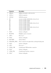
... B6 B9 7 FAN5 8 BP_PWR 9 CPU2 10 FAN4 11 BATTERY 12 DVD/TBU_PWR 13 FAN3 14 CPU1 15 CTRL_USB 16 FAN2 17 CTRL_PNL 18 FAN1 Description iDRAC6 Enterprise card connector SATA A connector SATA B connector memory module slot B1(white release lever) memory module slot B4 memory module slot B7 memory module slot...
... B6 B9 7 FAN5 8 BP_PWR 9 CPU2 10 FAN4 11 BATTERY 12 DVD/TBU_PWR 13 FAN3 14 CPU1 15 CTRL_USB 16 FAN2 17 CTRL_PNL 18 FAN1 Description iDRAC6 Enterprise card connector SATA A connector SATA B connector memory module slot B1(white release lever) memory module slot B4 memory module slot B7 memory module slot...

Hardware Manual
Page 193
...A protocol that provides remote management capabilities, crashed system recovery, and power control functions for Dell PowerEdge systems. IP - jumper - Kb - flash memory - Gram(s). A keyboard is an...and the peripheral device, typically a storage device. Kilobit(s); 1024 bits. FTP - G - Gb - GB - IPX - Kilo-; 1000. IPv6 - Each peripheral connection must be defined as x horizontal... on and running. g - In general, I /O - Input/output. Interrupt request. iDRAC, iDRAC6 - A type of changing the circuitry in a board. A controller that can be assigned an ...
...A protocol that provides remote management capabilities, crashed system recovery, and power control functions for Dell PowerEdge systems. IP - jumper - Kb - flash memory - Gram(s). A keyboard is an...and the peripheral device, typically a storage device. Kilobit(s); 1024 bits. FTP - G - Gb - GB - IPX - Kilo-; 1000. IPv6 - Each peripheral connection must be defined as x horizontal... on and running. g - In general, I /O - Input/output. Interrupt request. iDRAC, iDRAC6 - A type of changing the circuitry in a board. A controller that can be assigned an ...
Hardware Manual
Page 203
...removing, 82 troubleshooting, 166 heat sink, 138 hot-swap cooling fans, 100 hard drives, 80 power supplies, 86 I iDRAC Configuration Utility, 73 iDRAC6 Enterprise card installing, 94 removing, 95 indicators back panel, 19 front-panel, 12 NIC, 22 power, 12, 21 information tag removing, 78 replacing... 128 SAS backplane board, 147 SD card, 90 storage controller, 112 tape backup unit, 107 VFlash SD card, 96 Integrated Dell Remote Access Controller See iDRAC6 Enterprise card. internal SD flash card installing, 90 internal SD module installing, 88 removing, 90 internal USB cable installing, 93 ...
...removing, 82 troubleshooting, 166 heat sink, 138 hot-swap cooling fans, 100 hard drives, 80 power supplies, 86 I iDRAC Configuration Utility, 73 iDRAC6 Enterprise card installing, 94 removing, 95 indicators back panel, 19 front-panel, 12 NIC, 22 power, 12, 21 information tag removing, 78 replacing... 128 SAS backplane board, 147 SD card, 90 storage controller, 112 tape backup unit, 107 VFlash SD card, 96 Integrated Dell Remote Access Controller See iDRAC6 Enterprise card. internal SD flash card installing, 90 internal SD module installing, 88 removing, 90 internal USB cable installing, 93 ...

