
Hardware Manual
Page 7
... Unit 110 Integrated Storage Controller Card 111 Removing the Integrated Storage Controller Card 112 Installing the Integrated Storage Controller Card 112 RAID Battery 116 Removing a RAID Battery 116 Installing a RAID Battery 117 Cable Routing 118 Removing the Cable Retention Bracket 118 Installing the Cable Retention Bracket 119 Expansion Cards and Expansion-Card Risers...
... Unit 110 Integrated Storage Controller Card 111 Removing the Integrated Storage Controller Card 112 Installing the Integrated Storage Controller Card 112 RAID Battery 116 Removing a RAID Battery 116 Installing a RAID Battery 117 Cable Routing 118 Removing the Cable Retention Bracket 118 Installing the Cable Retention Bracket 119 Expansion Cards and Expansion-Card Risers...
Hardware Manual
Page 8
Removing Memory Modules 136 Processors 137 Removing a Processor 137 Installing a Processor 140 System Battery 141 Replacing the System Battery 141 Control Panel Assembly 143 Removing the Control Panel Display Module . . . 143 Installing the Control Panel Display Module . . . . 143 Removing the Control Panel Board 144 ...
Removing Memory Modules 136 Processors 137 Removing a Processor 137 Installing a Processor 140 System Battery 141 Replacing the System Battery 141 Control Panel Assembly 143 Removing the Control Panel Display Module . . . 143 Installing the Control Panel Display Module . . . . 143 Removing the Control Panel Board 144 ...
Hardware Manual
Page 9
Troubleshooting a NIC 155 Troubleshooting a Wet System 156 Troubleshooting a Damaged System 157 Troubleshooting the System Battery 158 Troubleshooting Power Supplies 158 Troubleshooting System Cooling Problems 159 Troubleshooting a Fan 160 Troubleshooting System ...a Storage Controller 167 Troubleshooting Expansion Cards 168 Troubleshooting the Processor(s 170 5 Running the System Diagnostics . . . . . 173 Using Dell™ PowerEdge™ Diagnostics 173 System Diagnostics Features 173 When to Use the System Diagnostics 174 Running the System Diagnostics 174 Contents 9
Troubleshooting a NIC 155 Troubleshooting a Wet System 156 Troubleshooting a Damaged System 157 Troubleshooting the System Battery 158 Troubleshooting Power Supplies 158 Troubleshooting System Cooling Problems 159 Troubleshooting a Fan 160 Troubleshooting System ...a Storage Controller 167 Troubleshooting Expansion Cards 168 Troubleshooting the Processor(s 170 5 Running the System Diagnostics . . . . . 173 Using Dell™ PowerEdge™ Diagnostics 173 System Diagnostics Features 173 When to Use the System Diagnostics 174 Running the System Diagnostics 174 Contents 9
Hardware Manual
Page 24
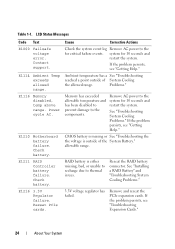
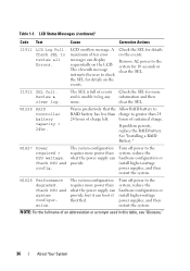
... critical failure events. Problems." Remove AC power to the for 10 seconds and restart the system. E1210 Motherboard battery failure. Check battery. Ambient temperature has a See "Troubleshooting reached a point outside of System Cooling the allowed range. Memory has exceeded...thermal issues. Table 1-1. allowable range. Reseat the RAID battery connector. Contact support. Reseat PCIe cards. See "Installing a RAID Battery" and "Troubleshooting System Cooling Problems." 3.3V voltage regulator has failed. CMOS battery is missing or See "Troubleshooting the the voltage is ...
... critical failure events. Problems." Remove AC power to the for 10 seconds and restart the system. E1210 Motherboard battery failure. Check battery. Ambient temperature has a See "Troubleshooting reached a point outside of System Cooling the allowed range. Memory has exceeded...thermal issues. Table 1-1. allowable range. Reseat the RAID battery connector. Contact support. Reseat PCIe cards. See "Installing a RAID Battery" and "Troubleshooting System Cooling Problems." 3.3V voltage regulator has failed. CMOS battery is missing or See "Troubleshooting the the voltage is ...
Hardware Manual
Page 36
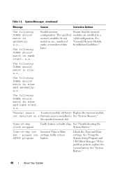
...system, reduce the hardware configuration or install higher-wattage power supplies, and then restart the system. Warns predictively that the Allow RAID battery to RAID battery has less than charge to greater than what the power supply can provide, but it can boot if throttled. The system configuration ... clear the SEL. Remove AC power to log any more power than 24 24 hours of ten error messages can provide. W1228 RAID Controller battery capacity < 24hr. hours of an abbreviation or acronym used in this table, see "Glossary." 36 About Your System Check PSU and config....
...system, reduce the hardware configuration or install higher-wattage power supplies, and then restart the system. Warns predictively that the Allow RAID battery to RAID battery has less than charge to greater than what the power supply can provide, but it can boot if throttled. The system configuration ... clear the SEL. Remove AC power to log any more power than 24 24 hours of ten error messages can provide. W1228 RAID Controller battery capacity < 24hr. hours of an abbreviation or acronym used in this table, see "Glossary." 36 About Your System Check PSU and config....
Hardware Manual
Page 48
...memory modules do not valid configuration. Thermal sensor A memory module without a Replace the memory module. See "Troubleshooting the System Battery." Time-of data Installation Guidelines." Check the Time and Date settings. please run settings; the specified memory slot Time-of-day ...clock stopped Faulty battery or faulty chip. If the problem persists, replace the system battery. See "System Battery." 48 About Your System See "Using the System Setup Program and UEFI Boot Manager...
...memory modules do not valid configuration. Thermal sensor A memory module without a Replace the memory module. See "Troubleshooting the System Battery." Time-of data Installation Guidelines." Check the Time and Date settings. please run settings; the specified memory slot Time-of-day ...clock stopped Faulty battery or faulty chip. If the problem persists, replace the system battery. See "System Battery." 48 About Your System See "Using the System Setup Program and UEFI Boot Manager...
Hardware Manual
Page 76
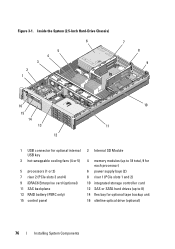
... for optional internal USB key 3 hot-swappable cooling fans (4 or 5) 5 processors (1 or 2) 7 riser 2 (PCIe slots 3 and 4) 9 iDRAC6 Enterprise card (optional) 11 SAS backplane 13 RAID battery (PERC only) 15 control panel 2 Internal SD Module 4 memory modules (up to 18 total, 9 for each processor) 6 power supply bays (2) 8 riser 1 (PCIe slots 1 and 2) 10...
... for optional internal USB key 3 hot-swappable cooling fans (4 or 5) 5 processors (1 or 2) 7 riser 2 (PCIe slots 3 and 4) 9 iDRAC6 Enterprise card (optional) 11 SAS backplane 13 RAID battery (PERC only) 15 control panel 2 Internal SD Module 4 memory modules (up to 18 total, 9 for each processor) 6 power supply bays (2) 8 riser 1 (PCIe slots 1 and 2) 10...
Hardware Manual
Page 112
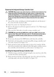
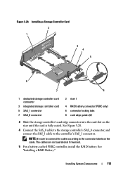
...data was not cleared at system shutdown. 5 If necessary, disconnect the RAID battery cable from the electrical outlet. 2 Open the system. Removing the Integrated Storage Controller Card CAUTION: Many repairs may only be done by Dell is adjacent to the blue guide, and then remove the controller out towards the...Figure 3-20. 7 Bend outward on both card-edge guides outward and pull the storage controller card out of the connector. CAUTION: Disconnecting the RAID battery cable from a PERC card can cause data loss if the "dirty cache" LED on the blue card-edge guide, lower the card onto the ...
...data was not cleared at system shutdown. 5 If necessary, disconnect the RAID battery cable from the electrical outlet. 2 Open the system. Removing the Integrated Storage Controller Card CAUTION: Many repairs may only be done by Dell is adjacent to the blue guide, and then remove the controller out towards the...Figure 3-20. 7 Bend outward on both card-edge guides outward and pull the storage controller card out of the connector. CAUTION: Disconnecting the RAID battery cable from a PERC card can cause data loss if the "dirty cache" LED on the blue card-edge guide, lower the card onto the ...
Hardware Manual
Page 113
...Be sure to connect the cable according to the controller's SAS_1 connector. The cables are not operational if reversed. 5 For a battery-cached PERC controller, install the RAID battery. Figure 3-20. Installing a Storage Controller Card 2 1 3 4 5 8 7 6 1 dedicated storage controller card connector ...3 integrated storage controller card 5 SAS_1 connector 7 SAS_0 connector 2 riser 1 4 RAID battery connector (PERC only) 6 connector locking tabs 8 card edge guides (2) 3 Slide the storage controller's card edge connector into the card ...
...Be sure to connect the cable according to the controller's SAS_1 connector. The cables are not operational if reversed. 5 For a battery-cached PERC controller, install the RAID battery. Figure 3-20. Installing a Storage Controller Card 2 1 3 4 5 8 7 6 1 dedicated storage controller card connector ...3 integrated storage controller card 5 SAS_1 connector 7 SAS_0 connector 2 riser 1 4 RAID battery connector (PERC only) 6 connector locking tabs 8 card edge guides (2) 3 Slide the storage controller's card edge connector into the card ...
Hardware Manual
Page 114
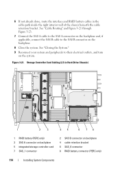
...of the chassis beneath the cable retention bracket. 6 If not already done, route the interface and RAID battery cables in Hard-Drive Chassis) 1 2 3 45 6 78 1 RAID battery (PERC only) 3 SAS A connector on backplane 5 integrated storage controller card 7 SAS_1 connector 2 SAS... B connector on backplane 4 cable retention bracket 6 SAS_0 connector 8 RAID battery connector (PERC only) 114 Installing System Components See "Closing ...
...of the chassis beneath the cable retention bracket. 6 If not already done, route the interface and RAID battery cables in Hard-Drive Chassis) 1 2 3 45 6 78 1 RAID battery (PERC only) 3 SAS A connector on backplane 5 integrated storage controller card 7 SAS_1 connector 2 SAS... B connector on backplane 4 cable retention bracket 6 SAS_0 connector 8 RAID battery connector (PERC only) 114 Installing System Components See "Closing ...
Hardware Manual
Page 115
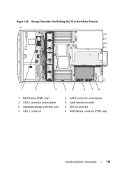
Figure 3-22. Storage Controller Card Cabling (Six 3.5-in Hard-Drive Chassis) 1 2 3 45 6 78 1 RAID battery (PERC only) 3 SAS A connector on backplane 5 integrated storage controller card 7 SAS_1 connector 2 SAS B connector on backplane 4 cable retention bracket 6 SAS_0 connector 8 RAID battery connector (PERC only) Installing System Components 115
Figure 3-22. Storage Controller Card Cabling (Six 3.5-in Hard-Drive Chassis) 1 2 3 45 6 78 1 RAID battery (PERC only) 3 SAS A connector on backplane 5 integrated storage controller card 7 SAS_1 connector 2 SAS B connector on backplane 4 cable retention bracket 6 SAS_0 connector 8 RAID battery connector (PERC only) Installing System Components 115
Hardware Manual
Page 116
... A connector on the right edge of the battery bay and draw out the RAID battery from the battery carrier. 2 Disconnect the cable between the RAID battery and the storage controller card. Removing a RAID Battery 1 Pull back gently on backplane 4 integrated storage controller card 6 RAID battery connector (PERC only) RAID Battery The information in this section applies only...
... A connector on the right edge of the battery bay and draw out the RAID battery from the battery carrier. 2 Disconnect the cable between the RAID battery and the storage controller card. Removing a RAID Battery 1 Pull back gently on backplane 4 integrated storage controller card 6 RAID battery connector (PERC only) RAID Battery The information in this section applies only...
Hardware Manual
Page 117
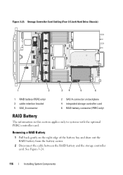
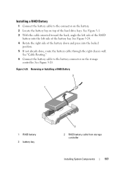
... through the right chassis wall. See "Cable Routing." 6 Connect the battery cable to the connector on the battery. 2 Locate the battery bay on the storage controller. Figure 3-24. See Figure 3-24. 4 Rotate the right side of the battery bay. Removing or Installing a RAID Battery 2 1 1 RAID battery 3 battery bay 3 2 RAID battery cable from storage controller Installing System Components 117
... through the right chassis wall. See "Cable Routing." 6 Connect the battery cable to the connector on the battery. 2 Locate the battery bay on the storage controller. Figure 3-24. See Figure 3-24. 4 Rotate the right side of the battery bay. Removing or Installing a RAID Battery 2 1 1 RAID battery 3 battery bay 3 2 RAID battery cable from storage controller Installing System Components 117
Hardware Manual
Page 141
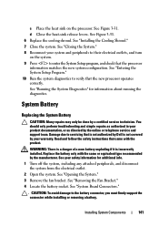
...Shroud." 7 Close the system. See your warranty. Damage due to enter the System Setup program, and check that is not authorized by Dell is incorrectly installed. See "System Board Connectors." . See "Closing the System." 8 Reconnect your product documentation, or as directed by ...Place the heat sink on the system. 9 Press to servicing that the processor information matches the new system configuration. System Battery Replacing the System Battery CAUTION: Many repairs may only be done by your safety information for information about running the diagnostics. WARNING: There is ...
...Shroud." 7 Close the system. See your warranty. Damage due to enter the System Setup program, and check that is not authorized by Dell is incorrectly installed. See "System Board Connectors." . See "Closing the System." 8 Reconnect your product documentation, or as directed by ...Place the heat sink on the system. 9 Press to servicing that the processor information matches the new system configuration. System Battery Replacing the System Battery CAUTION: Many repairs may only be done by your safety information for information about running the diagnostics. WARNING: There is ...
Hardware Manual
Page 142
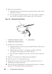
...outlet and turn the system on the positive side of the connector. Replacing the System Battery 1 2 3 1 positive side of battery connector 3 negative side of the connector. a Support the battery connector by pressing down firmly on the positive side of the connector. See "Closing the... System." 9 Reconnect the system to confirm that the battery is operating properly. 5 Remove the system battery. Figure 3-33. See "Entering the System Setup Program." 142 Installing System Components See "Replacing the Fan Bracket." ...
...outlet and turn the system on the positive side of the connector. Replacing the System Battery 1 2 3 1 positive side of battery connector 3 negative side of the connector. a Support the battery connector by pressing down firmly on the positive side of the connector. See "Closing the... System." 9 Reconnect the system to confirm that the battery is operating properly. 5 Remove the system battery. Figure 3-33. See "Entering the System Setup Program." 142 Installing System Components See "Replacing the Fan Bracket." ...
Hardware Manual
Page 151
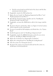
See "Installing the Integrated Storage Controller Card." 9 If applicable, reconnect the RAID battery cable to the storage controller card. 10 Reconnect all power and interface cables (see Figure 6-2 for the locations of the chassis until the blue retention ...
See "Installing the Integrated Storage Controller Card." 9 If applicable, reconnect the RAID battery cable to the storage controller card. 10 Reconnect all power and interface cables (see Figure 6-2 for the locations of the chassis until the blue retention ...
Hardware Manual
Page 158
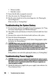
... one power supply must be done by the power supply's status indicator. Read and follow the safety instructions that is not authorized by Dell is not resolved by the online or telephone service and support team. See "Power Indicator Codes." 158 Troubleshooting Your System CAUTION: Many repairs...-enter the time and date through the System Setup program. If the date and time are properly connected. 5 Close the system. See "System Battery." • Memory modules • Hard-drive carriers 4 Ensure that all cables are not correct in your warranty. See "Closing the System." 6 ...
... one power supply must be done by the power supply's status indicator. Read and follow the safety instructions that is not authorized by Dell is not resolved by the online or telephone service and support team. See "Power Indicator Codes." 158 Troubleshooting Your System CAUTION: Many repairs...-enter the time and date through the System Setup program. If the date and time are properly connected. 5 Close the system. See "System Battery." • Memory modules • Hard-drive carriers 4 Ensure that all cables are not correct in your warranty. See "Closing the System." 6 ...
Hardware Manual
Page 168
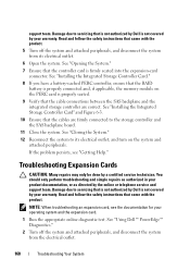
... should only perform troubleshooting and simple repairs as directed by the online or telephone service and support team. See "Using Dell™ PowerEdge™ Diagnostics." 2 Turn off the system and attached peripherals, and disconnect the system from the electrical outlet. 168 ...electrical outlet. 6 Open the system. See "Installing the Integrated Storage Controller Card." 8 If you have a battery-cached PERC controller, ensure that the RAID battery is properly connected and, if applicable, the memory module on the system and attached peripherals. NOTE: When troubleshooting...
... should only perform troubleshooting and simple repairs as directed by the online or telephone service and support team. See "Using Dell™ PowerEdge™ Diagnostics." 2 Turn off the system and attached peripherals, and disconnect the system from the electrical outlet. 168 ...electrical outlet. 6 Open the system. See "Installing the Integrated Storage Controller Card." 8 If you have a battery-cached PERC controller, ensure that the RAID battery is properly connected and, if applicable, the memory module on the system and attached peripherals. NOTE: When troubleshooting...
Hardware Manual
Page 181
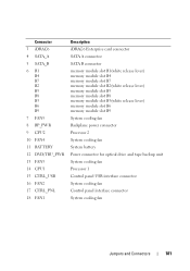
Connector 3 iDRAC6 4 SATA_A 5 SATA_B 6 B1 B4 B7 B2 B5 B8 B3 B6 B9 7 FAN5 8 BP_PWR 9 CPU2 10 FAN4 11 BATTERY 12 DVD/TBU_PWR 13 FAN3 14 CPU1 15 CTRL_USB 16 FAN2 17 CTRL_PNL 18 FAN1 Description iDRAC6 Enterprise card connector SATA A connector SATA B connector ... slot B3(white release lever) memory module slot B6 memory module slot B9 System cooling fan Backplane power connector Processor 2 System cooling fan System battery Power connector for optical drive and tape backup unit System cooling fan Processor 1 Control panel USB interface connector System cooling fan Control panel interface connector...
Connector 3 iDRAC6 4 SATA_A 5 SATA_B 6 B1 B4 B7 B2 B5 B8 B3 B6 B9 7 FAN5 8 BP_PWR 9 CPU2 10 FAN4 11 BATTERY 12 DVD/TBU_PWR 13 FAN3 14 CPU1 15 CTRL_USB 16 FAN2 17 CTRL_PNL 18 FAN1 Description iDRAC6 Enterprise card connector SATA A connector SATA B connector ... slot B3(white release lever) memory module slot B6 memory module slot B9 System cooling fan Backplane power connector Processor 2 System cooling fan System battery Power connector for optical drive and tape backup unit System cooling fan Processor 1 Control panel USB interface connector System cooling fan Control panel interface connector...

Hardware Manual
Page 198
...when referring to 1,000,000,000,000 bytes. TCP/IP offload engine. A technology that offloads network processing to your system's RAM. UDIMM - USB - USB devices can display (with the monitor) your system in addition to the network controller. See memory...and down. Video resolution (800 x 600, for example. Transmission Control Protocol/Internet Protocol. An unregistered (unbuffered) DDR3 memory module. A battery-powered unit that provides (in combination with the appropriate video drivers and monitor capabilities). A program used to connect to your system's video ...
...when referring to 1,000,000,000,000 bytes. TCP/IP offload engine. A technology that offloads network processing to your system's RAM. UDIMM - USB - USB devices can display (with the monitor) your system in addition to the network controller. See memory...and down. Video resolution (800 x 600, for example. Transmission Control Protocol/Internet Protocol. An unregistered (unbuffered) DDR3 memory module. A battery-powered unit that provides (in combination with the appropriate video drivers and monitor capabilities). A program used to connect to your system's video ...


