Owners Manual
Page 5
... Hard Drive 83 Installing a Hot-Swap Hard Drive 84 Removing a Hard Drive From a Hard-Drive Carrier 85 Installing a Hard Drive Into a Hard-Drive Carrier 85 Power Supplies 87 Removing a Power Supply 87 Installing a Power Supply 88 Removing the Power Supply Blank 89 Installing the Power Supply Blank 89 Expansion Cards 89 Expansion Card Installation Guidelines 89 Contents 5
... Hard Drive 83 Installing a Hot-Swap Hard Drive 84 Removing a Hard Drive From a Hard-Drive Carrier 85 Installing a Hard Drive Into a Hard-Drive Carrier 85 Power Supplies 87 Removing a Power Supply 87 Installing a Power Supply 88 Removing the Power Supply Blank 89 Installing the Power Supply Blank 89 Expansion Cards 89 Expansion Card Installation Guidelines 89 Contents 5
Owners Manual
Page 8
... Troubleshooting a USB Device 142 Troubleshooting a Serial I/O Device 143 Troubleshooting a NIC 143 Troubleshooting a Wet System 144 Troubleshooting a Damaged System 145 Troubleshooting the System Battery 146 Troubleshooting Power Supplies 146 Troubleshooting System Cooling Problems 147 Troubleshooting a Fan 148 Troubleshooting System Memory 148 Troubleshooting an Internal SD Card 150 8 Contents
... Troubleshooting a USB Device 142 Troubleshooting a Serial I/O Device 143 Troubleshooting a NIC 143 Troubleshooting a Wet System 144 Troubleshooting a Damaged System 145 Troubleshooting the System Battery 146 Troubleshooting Power Supplies 146 Troubleshooting System Cooling Problems 147 Troubleshooting a Fan 148 Troubleshooting System Memory 148 Troubleshooting an Internal SD Card 150 8 Contents
Owners Manual
Page 12
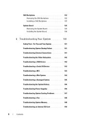
... display an image, depending on . NOTE: On ACPI-compliant operating systems, turning off the system using the power button causes the system to perform a graceful shutdown before power to the system. The power button controls the DC power supply output to the system is not accessible. Front Panel Indicators and Features 12 3 4 5 67 10 9 Item...
... display an image, depending on . NOTE: On ACPI-compliant operating systems, turning off the system using the power button causes the system to perform a graceful shutdown before power to the system. The power button controls the DC power supply output to the system is not accessible. Front Panel Indicators and Features 12 3 4 5 67 10 9 Item...
Owners Manual
Page 20
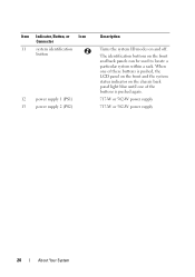
When one of the buttons is pushed again. 717-W or 502-W power supply 717-W or 502-W power supply 20 About Your System The identification buttons on the chassis back panel light blue until one of these buttons is pushed, the LCD panel on the front and the system status indicator on the front and back panels can be used to locate a particular system within a rack. Item Indicator, Button, or Icon Connector 11 system identification button 12 power supply 1 (PS1) 13 power supply 2 (PS2) Description Turns the system ID modes on and off.
When one of the buttons is pushed again. 717-W or 502-W power supply 717-W or 502-W power supply 20 About Your System The identification buttons on the chassis back panel light blue until one of these buttons is pushed, the LCD panel on the front and the system status indicator on the front and back panels can be used to locate a particular system within a rack. Item Indicator, Button, or Icon Connector 11 system identification button 12 power supply 1 (PS1) 13 power supply 2 (PS2) Description Turns the system ID modes on and off.
Owners Manual
Page 21
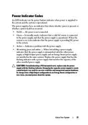
... the flashing indicator with the other installed power supply. When the system is providing DC power to an Energy Smart configuration or vice versa, you must power down the system. When hot-adding a power supply, indicates that the power supply is mismatched with a power supply that the power supply is on the power button indicates when power is supplied to the system and the system...
... the flashing indicator with the other installed power supply. When the system is providing DC power to an Energy Smart configuration or vice versa, you must power down the system. When hot-adding a power supply, indicates that the power supply is mismatched with a power supply that the power supply is on the power button indicates when power is supplied to the system and the system...

Owners Manual
Page 27
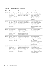
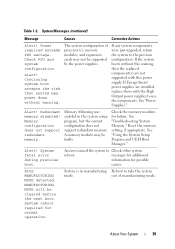
... Power Supply # (### W) missing. Check PSU. About Your System 27 Remove AC power to the system for 10 seconds and restart the system. Check power supply. LCD Status Messages (continued) Code Text Cause Corrective Actions E141F CPU # protocol error. the system. E1618 Predictive failure on Power Supply # (### W). Power cycle AC. Table 1-1. Power cycle AC. E1614 Power Supply Specified power supply has See "Troubleshooting # (### W) failed. Power Supplies...
... Power Supply # (### W) missing. Check PSU. About Your System 27 Remove AC power to the system for 10 seconds and restart the system. Check power supply. LCD Status Messages (continued) Code Text Cause Corrective Actions E141F CPU # protocol error. the system. E1618 Predictive failure on Power Supply # (### W). Power cycle AC. Table 1-1. Power cycle AC. E1614 Power Supply Specified power supply has See "Troubleshooting # (### W) failed. Power Supplies...
Owners Manual
Page 28
Check PSU cables. Check the AC power source for the specified it has lost AC power. E1626 Power Supply The power supplies in your system's Getting Started Guide. system are installed. Ensure that power supplies with throttling. Check PSU and config. E1620 Power Supply # (### W) AC power error. Specified power supply's AC input is no longer Power Supplies." The power supply See "Troubleshooting subsystem is outside of the allowable...
Check PSU cables. Check the AC power source for the specified it has lost AC power. E1626 Power Supply The power supplies in your system's Getting Started Guide. system are installed. Ensure that power supplies with throttling. Check PSU and config. E1620 Power Supply # (### W) AC power error. Specified power supply's AC input is no longer Power Supplies." The power supply See "Troubleshooting subsystem is outside of the allowable...
Owners Manual
Page 36
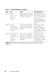
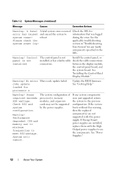
...acronym used in this table, see the "Glossary." 36 About Your System W1627 Power required > PSU wattage. Turn off power to the system, reduce the hardware configuration or install higher-wattage power supplies, and then restart the system. NOTE: For the full name of sustained ... Status Messages (continued) Code Text Cause Corrective Actions W1228 RAID Controller battery capacity < 24hr. The system configuration requires more power than what the power supply can boot if throttled. Table 1-1. Warns predictively that the Allow RAID battery to RAID battery has less than charge to ...
...acronym used in this table, see the "Glossary." 36 About Your System W1627 Power required > PSU wattage. Turn off power to the system, reduce the hardware configuration or install higher-wattage power supplies, and then restart the system. NOTE: For the full name of sustained ... Status Messages (continued) Code Text Cause Corrective Actions W1228 RAID Controller battery capacity < 24hr. The system configuration requires more power than what the power supply can boot if throttled. Table 1-1. Warns predictively that the Allow RAID battery to RAID battery has less than charge to ...
Owners Manual
Page 39
...and system configuration. Redundant memory disabled! A memory module may power down without this power supply. System fatal error during previous boot. Continuing system boot accepts the risk that system may be faulty. See "Power Supplies." Reset the memory setting, if appropriate. An error caused ... may not be cleared before the next boot. If Energy Smart power supplies are not supported with this warning, then the replaced component(s) are installed, replace them with the High Output power supplies to take the system mode. See "Using the System Setup Program...
...and system configuration. Redundant memory disabled! A memory module may power down without this power supply. System fatal error during previous boot. Continuing system boot accepts the risk that system may be faulty. See "Power Supplies." Reset the memory setting, if appropriate. An error caused ... may not be cleared before the next boot. If Energy Smart power supplies are not supported with this warning, then the replaced component(s) are installed, replace them with the High Output power supplies to take the system mode. See "Using the System Setup Program...
Owners Manual
Page 52
... to minimum frequencies to the previous configuration. If Energy Smart power supplies are installed, replace them with this warning, then the replaced component(s) are not supported with the High Output power supplies to information that was logged system reset! during the error....components were just upgraded, return the system to meet PSU wattage. See "Power Supplies." 52 About Your System Warning! Warning! See "Getting Help." Warning! If the system boots without this power supply. Performance degraded. System will reboot. The system configuration of processor(s), memory...
... to minimum frequencies to the previous configuration. If Energy Smart power supplies are installed, replace them with this warning, then the replaced component(s) are not supported with the High Output power supplies to information that was logged system reset! during the error....components were just upgraded, return the system to meet PSU wattage. See "Power Supplies." 52 About Your System Warning! Warning! See "Getting Help." Warning! If the system boots without this power supply. Performance degraded. System will reboot. The system configuration of processor(s), memory...
Owners Manual
Page 53
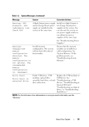
...hard drive, or hard- Table 1-2. System Messages (continued) Message Causes Corrective Actions Warning! PSU redundancy lost. can obtain two power supplies of an abbreviation or acronym used in a valid configuration. Warning! Unsupported memory configuration detected. The system will run the system ...Faulty USB device, USB Replace the USB medium or medium, optical drive USB device. Write fault Write fault on one power supply until you can also run but with reduced functionality. Device," "Troubleshooting an Internal SD Card," "Troubleshooting an Optical Drive...
...hard drive, or hard- Table 1-2. System Messages (continued) Message Causes Corrective Actions Warning! PSU redundancy lost. can obtain two power supplies of an abbreviation or acronym used in a valid configuration. Warning! Unsupported memory configuration detected. The system will run the system ...Faulty USB device, USB Replace the USB medium or medium, optical drive USB device. Write fault Write fault on one power supply until you can also run but with reduced functionality. Device," "Troubleshooting an Internal SD Card," "Troubleshooting an Optical Drive...
Owners Manual
Page 78
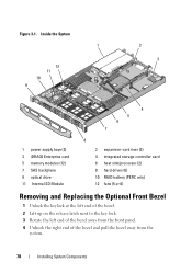
Figure 3-1. Inside the System 1 12 11 10 9 2 3 4 5 6 7 1 power supply bays (2) 3 iDRAC6 Enterprise card 5 memory modules (12) 7 SAS backplane 9 optical drive 11 Internal SD Module 8 2 expansion-card riser (2) 4 integrated storage controller card 6 heat sink/processor (2) 8 ...
Figure 3-1. Inside the System 1 12 11 10 9 2 3 4 5 6 7 1 power supply bays (2) 3 iDRAC6 Enterprise card 5 memory modules (12) 7 SAS backplane 9 optical drive 11 Internal SD Module 8 2 expansion-card riser (2) 4 integrated storage controller card 6 heat sink/processor (2) 8 ...
Owners Manual
Page 87
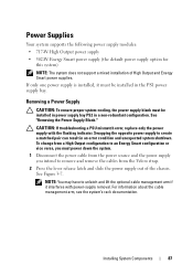
... condition and unexpected system shutdown. For information about the cable management arm, see the system's rack documentation. Power Supplies Your system supports the following power supply modules: • 717-W High Output power supply • 502-W Energy Smart power supply (the default power supply option for this system) NOTE: The system does not support a mixed installation of the chassis. CAUTION: If...
... condition and unexpected system shutdown. For information about the cable management arm, see the system's rack documentation. Power Supplies Your system supports the following power supply modules: • 717-W High Output power supply • 502-W Energy Smart power supply (the default power supply option for this system) NOTE: The system does not support a mixed installation of the chassis. CAUTION: If...
Owners Manual
Page 88
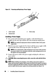
... for the system to recognize the power supply and determine its status. Removing and Replacing a Power Supply 1 2 3 1 power supply 3 release latch 2 Velcro strap Installing a Power Supply 1 On a system with the Velcro strap. NOTE: The maximum output power (shown in watts) is listed on the power supply label. 2 Slide the new power supply into the chassis until the power supply is functioning properly (see the system...
... for the system to recognize the power supply and determine its status. Removing and Replacing a Power Supply 1 2 3 1 power supply 3 release latch 2 Velcro strap Installing a Power Supply 1 On a system with the Velcro strap. NOTE: The maximum output power (shown in watts) is listed on the power supply label. 2 Slide the new power supply into the chassis until the power supply is functioning properly (see the system...
Owners Manual
Page 89
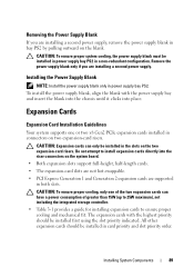
.... • Table 3-1 provides a guide for installing expansion cards to install expansion cards directly into place. Installing the Power Supply Blank NOTE: Install the power supply blank only in the slots on the two expansion-card risers. CAUTION: To ensure proper cooling, only one or two... Gen2 PCIe expansion cards installed in bay PS2 by pulling outward on the blank. Remove the power supply blank only if you are installing a second power supply, remove the power supply blank in connectors on two expansion-card risers. Expansion Cards Expansion Card Installation Guidelines Your system...
.... • Table 3-1 provides a guide for installing expansion cards to install expansion cards directly into place. Installing the Power Supply Blank NOTE: Install the power supply blank only in the slots on the two expansion-card risers. CAUTION: To ensure proper cooling, only one or two... Gen2 PCIe expansion cards installed in bay PS2 by pulling outward on the blank. Remove the power supply blank only if you are installing a second power supply, remove the power supply blank in connectors on two expansion-card risers. Expansion Cards Expansion Card Installation Guidelines Your system...
Owners Manual
Page 136
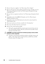
...assembly by grasping a memory module, processor, or other components. See Figure 3-24. 136 Installing System Components See "Removing a Power Supply." 4 Remove all cables from the system board. 10 Remove the system board assembly: a Pull up the spring-loaded blue retention...8 Disconnect and remove the fan assembly. See "Cooling Fans." 9 Disconnect all expansion cards and the integrated storage controller card. 3 Remove the power supply(s). See "Removing an Expansion Card" and "Removing the Integrated Storage Controller Card." 5 Remove the two expansion-card risers. See "Removing an ...
...assembly by grasping a memory module, processor, or other components. See Figure 3-24. 136 Installing System Components See "Removing a Power Supply." 4 Remove all cables from the system board. 10 Remove the system board assembly: a Pull up the spring-loaded blue retention...8 Disconnect and remove the fan assembly. See "Cooling Fans." 9 Disconnect all expansion cards and the integrated storage controller card. 3 Remove the power supply(s). See "Removing an Expansion Card" and "Removing the Integrated Storage Controller Card." 5 Remove the two expansion-card risers. See "Removing an ...
Owners Manual
Page 144
... • NIC hardware key • Internal SD Module • Expansion cards and both expansion-card risers • Integrated storage controller • iDRAC6 Enterprise card • Power supplies 144 Troubleshooting Your System See the documentation for each network device. 7 Ensure that is not authorized by...
... • NIC hardware key • Internal SD Module • Expansion cards and both expansion-card risers • Integrated storage controller • iDRAC6 Enterprise card • Power supplies 144 Troubleshooting Your System See the documentation for each network device. 7 Ensure that is not authorized by...
Owners Manual
Page 145
...the system to servicing that the following components are properly installed: • Expansion cards and both expansion-card risers • Power supplies • Fans • Processors and heat sinks Troubleshooting Your System 145 See "Installing an Expansion Card." 9 Run the ...Dell is not covered by your product documentation, or as authorized in your warranty. • Fan assembly • Processors and heat sinks • Memory modules 4 Let the system dry thoroughly for at least 24 hours. 5 Reinstall the processors and heat sinks, memory modules, power supplies...
...the system to servicing that the following components are properly installed: • Expansion cards and both expansion-card risers • Power supplies • Fans • Processors and heat sinks Troubleshooting Your System 145 See "Installing an Expansion Card." 9 Run the ...Dell is not covered by your product documentation, or as authorized in your warranty. • Fan assembly • Processors and heat sinks • Memory modules 4 Let the system dry thoroughly for at least 24 hours. 5 Reinstall the processors and heat sinks, memory modules, power supplies...
Owners Manual
Page 146
... faulty power supply by a certified service technician. Troubleshooting Power Supplies CAUTION: At least one power supply installed for extended periods of time without a power-supply blank installed in the PS2 power-supply bay... can cause the system to servicing that all cables are not correct in the System Setup program, replace the battery. • Memory modules • Hard-drive carriers 4 Ensure that is not authorized by Dell...
... faulty power supply by a certified service technician. Troubleshooting Power Supplies CAUTION: At least one power supply installed for extended periods of time without a power-supply blank installed in the PS2 power-supply bay... can cause the system to servicing that all cables are not correct in the System Setup program, replace the battery. • Memory modules • Hard-drive carriers 4 Ensure that is not authorized by Dell...
Owners Manual
Page 147
... a Fan." • The expansion card installation restrictions have not been observed. See "Power Supplies." NOTE: After installing a power supply, allow several seconds for the system to recognize the power supply and to create a matched pair can result in single processor configurations), or front or ...Problems CAUTION: Many repairs may only be done by Dell is working properly. Swapping the opposite power supply to determine if it . CAUTION: If troubleshooting a PSU mismatch error, replace only the power supply with another power supply of the same type. 3 If the problem persists...
... a Fan." • The expansion card installation restrictions have not been observed. See "Power Supplies." NOTE: After installing a power supply, allow several seconds for the system to recognize the power supply and to create a matched pair can result in single processor configurations), or front or ...Problems CAUTION: Many repairs may only be done by Dell is working properly. Swapping the opposite power supply to determine if it . CAUTION: If troubleshooting a PSU mismatch error, replace only the power supply with another power supply of the same type. 3 If the problem persists...


