
Owners Manual
Page 13
..., Button, or Icon Connector 2 NMI button 3 USB connectors (2) 4 Video connector 5 LCD menu buttons 6 LCD panel 7 System identification button Description Used to troubleshoot software and device driver errors when using the end of the buttons is pushed again. The LCD lights amber when the system needs attention, and the LCD panel displays...
..., Button, or Icon Connector 2 NMI button 3 USB connectors (2) 4 Video connector 5 LCD menu buttons 6 LCD panel 7 System identification button Description Used to troubleshoot software and device driver errors when using the end of the buttons is pushed again. The LCD lights amber when the system needs attention, and the LCD panel displays...
Owners Manual
Page 64
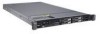
...PXE support allows the system to monitor the operating system for the NIC. Capability Detected Displays the features of an additional driver. When Enabled, the operating system is not initialized. NOTE: Some NIC features may also be accessed through the system's management controller.)... Embedded Gb NICx (NIC1 default: Enabled with operating systems that support WDAT implementations of the Advanced Configuration and Power Interface (ACPI) 3.0b ...
...PXE support allows the system to monitor the operating system for the NIC. Capability Detected Displays the features of an additional driver. When Enabled, the operating system is not initialized. NOTE: Some NIC features may also be accessed through the system's management controller.)... Embedded Gb NICx (NIC1 default: Enabled with operating systems that support WDAT implementations of the Advanced Configuration and Power Interface (ACPI) 3.0b ...

Owners Manual
Page 130
Figure 3-22. Control Panel Removal 3 2 1 4 5 6 7 1 front panel screw (Torx) 3 control panel board 5 USB cable 7 display module 2 display module cable 4 control panel cable 6 mounting screws (3 Torx) 16 Using a T10 Torx driver, remove the two screws that secure the display module to the system chassis. 17 Remove the display module from the chassis cutout. 130 Installing System Components
Figure 3-22. Control Panel Removal 3 2 1 4 5 6 7 1 front panel screw (Torx) 3 control panel board 5 USB cable 7 display module 2 display module cable 4 control panel cable 6 mounting screws (3 Torx) 16 Using a T10 Torx driver, remove the two screws that secure the display module to the system chassis. 17 Remove the display module from the chassis cutout. 130 Installing System Components

Owners Manual
Page 131
... the control panel cable and USB cable from the control panel board. Damage due to unseat the connector. See Figure 3-22. 7 Using a T10 Torx driver, remove the three screws that came with the two Torx screws. Removing the Control Panel Board CAUTION: Many repairs may only be done by a certified... 131 See "Closing the System." 5 Reconnect the system to the power source and turn on the cable to servicing that is not authorized by Dell is not covered by the online or telephone service and support team. See Figure 3-22. 5 If applicable, disconnect the Internal SD Module cable ...
... the control panel cable and USB cable from the control panel board. Damage due to unseat the connector. See Figure 3-22. 7 Using a T10 Torx driver, remove the three screws that came with the two Torx screws. Removing the Control Panel Board CAUTION: Many repairs may only be done by a certified... 131 See "Closing the System." 5 Reconnect the system to the power source and turn on the cable to servicing that is not authorized by Dell is not covered by the online or telephone service and support team. See Figure 3-22. 5 If applicable, disconnect the Internal SD Module cable ...

Owners Manual
Page 143
..., replace the USB cable if applicable, and power up the device. If all cable connections. • If the activity indicator does not light, the network driver files might be damaged or missing. • Enable autonegotiation. • Use another connector on the system and the serial device.
..., replace the USB cable if applicable, and power up the device. If all cable connections. • If the activity indicator does not light, the network driver files might be damaged or missing. • Enable autonegotiation. • Use another connector on the system and the serial device.
Owners Manual
Page 144
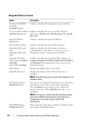
4 Ensure that the appropriate drivers are installed and the protocols are all set to servicing that is not authorized by Dell is not covered by your product documentation, or as directed by a certified service technician. See "Integrated Devices Screen." 6 Ensure that came with the product. 1 Turn ...
4 Ensure that the appropriate drivers are installed and the protocols are all set to servicing that is not authorized by Dell is not covered by your product documentation, or as directed by a certified service technician. See "Integrated Devices Screen." 6 Ensure that came with the product. 1 Turn ...

Owners Manual
Page 152
... that came with the product. 1 If applicable, remove the bezel. Read and follow the safety instructions that is not authorized by Dell is not covered by your warranty. CAUTION: This troubleshooting procedure can destroy data stored on the system and attached peripherals. Damage due ...correctly 4 Enter the System Setup program and ensure that is not authorized by Dell is not covered by your warranty. See "Removing the Front Bezel." 2 Try using a different DVD. 3 Ensure that the device drivers for the optical drive are installed and are enabled. support team. Before you...
... that came with the product. 1 If applicable, remove the bezel. Read and follow the safety instructions that is not authorized by Dell is not covered by your warranty. CAUTION: This troubleshooting procedure can destroy data stored on the system and attached peripherals. Damage due ...correctly 4 Enter the System Setup program and ensure that is not authorized by Dell is not covered by your warranty. See "Removing the Front Bezel." 2 Try using a different DVD. 3 Ensure that the device drivers for the optical drive are installed and are enabled. support team. Before you...
Owners Manual
Page 153
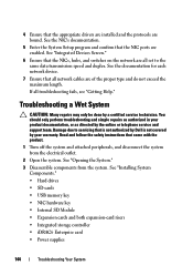
...." See "Removing the Front Bezel." 3 If your system has a SAS or PERC controller and your hard drives are configured correctly. b Ensure that the required device drivers for your controller card are installed and are configured in the System Setup program. If the problem persists, see the documentation for your operating system...
...." See "Removing the Front Bezel." 3 If your system has a SAS or PERC controller and your hard drives are configured correctly. b Ensure that the required device drivers for your controller card are installed and are configured in the System Setup program. If the problem persists, see the documentation for your operating system...

Owners Manual
Page 155
Damage due to servicing that is not authorized by Dell is not covered by your tape drive documentation for more information about device drivers. 3 Reinstall the tape-backup software as instructed in the tape-backup software documentation. 4 Ensure that the tape drive's ... be done by a certified service technician. See "Closing the System." 10 Reconnect the system to servicing that the device drivers for additional troubleshooting instructions. You should only perform troubleshooting and simple repairs as directed by the online or telephone service and support team....
Damage due to servicing that is not authorized by Dell is not covered by your tape drive documentation for more information about device drivers. 3 Reinstall the tape-backup software as instructed in the tape-backup software documentation. 4 Ensure that the tape drive's ... be done by a certified service technician. See "Closing the System." 10 Reconnect the system to servicing that the device drivers for additional troubleshooting instructions. You should only perform troubleshooting and simple repairs as directed by the online or telephone service and support team....

Owners Manual
Page 170
... add-in -line memory module. F - File allocation table. DHCP - Domain Name System. Electromagnetic interference. flash memory - A system's RAM is usually made up entirely of tests for peripherals, such as www.example.com, into an expansion-card connector on the system board. Error...unit. diagnostics - A method of electronic chip that plugs into IP addresses, such as 208.77.188.166. Dynamic random-access memory. driver - The Microsoft® Windows® operating systems can be programmed and 170 Glossary Double-data rate. ESD - ESM - Digital versatile...
... add-in -line memory module. F - File allocation table. DHCP - Domain Name System. Electromagnetic interference. flash memory - A system's RAM is usually made up entirely of tests for peripherals, such as www.example.com, into an expansion-card connector on the system board. Error...unit. diagnostics - A method of electronic chip that plugs into IP addresses, such as 208.77.188.166. Dynamic random-access memory. driver - The Microsoft® Windows® operating systems can be programmed and 170 Glossary Double-data rate. ESD - ESM - Digital versatile...

Owners Manual
Page 176
... module. utility - Volt(s) alternating current. VDC - Volt(s) direct current. The logical circuitry that provides (in combination with the appropriate video drivers and monitor capabilities). TCP/IP offload engine. UPS - A USB connector provides a single connection point for example) is expressed as the last... (with the monitor) your monitor must be an expansion card that automatically supplies power to your system in addition to your system's RAM. See memory key. video adapter - video resolution - TCP/IP - V - A video adapter may be integrated into the system...
... module. utility - Volt(s) alternating current. VDC - Volt(s) direct current. The logical circuitry that provides (in combination with the appropriate video drivers and monitor capabilities). TCP/IP offload engine. UPS - A USB connector provides a single connection point for example) is expressed as the last... (with the monitor) your monitor must be an expansion card that automatically supplies power to your system in addition to your system's RAM. See memory key. video adapter - video resolution - TCP/IP - V - A video adapter may be integrated into the system...


