Quick Reference Guide
Page 3
... Troubleshooting Tips 32 Resolving Software and Hardware Incompatibilities 32 Using Microsoft® Windows® XP System Restore 32 Using the Last Known Good Configuration 34 Dell Diagnostics 34 Before You Start Testing 36 Beep Codes 36 Error Messages 37 Diagnostic Lights 37 Frequently Asked Questions 42 Index 45 Contents 3
... Troubleshooting Tips 32 Resolving Software and Hardware Incompatibilities 32 Using Microsoft® Windows® XP System Restore 32 Using the Last Known Good Configuration 34 Dell Diagnostics 34 Before You Start Testing 36 Beep Codes 36 Error Messages 37 Diagnostic Lights 37 Frequently Asked Questions 42 Index 45 Contents 3
Quick Reference Guide
Page 5
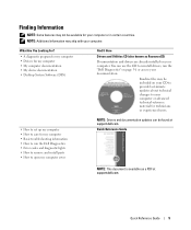
...up my computer • How to care for my computer • Basic troubleshooting information • How to run the Dell Diagnostics • Error codes and diagnostic lights • How to remove and install parts • How to open my computer cover NOTE: Drivers and documentation updates ...can use the CD to reinstall drivers, run the "Dell Diagnostics" on your documentation. Quick Reference Guide 5 Quick Reference Guide NOTE...
...up my computer • How to care for my computer • Basic troubleshooting information • How to run the Dell Diagnostics • Error codes and diagnostic lights • How to remove and install parts • How to open my computer cover NOTE: Drivers and documentation updates ...can use the CD to reinstall drivers, run the "Dell Diagnostics" on your documentation. Quick Reference Guide 5 Quick Reference Guide NOTE...
Quick Reference Guide
Page 19
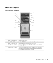
... 3.5-inch drive bay You can use the bay for an optional floppy drive or an optional Media Card Reader. 5 hard-drive activity light The hard drive light is operating. The light might also be on when a device such as your CD player is on when the computer reads data from or writes data...
... 3.5-inch drive bay You can use the bay for an optional floppy drive or an optional Media Card Reader. 5 hard-drive activity light The hard drive light is operating. The light might also be on when a device such as your CD player is on when the computer reads data from or writes data...
Quick Reference Guide
Page 20
.... Use the headphone connector to indicate different states: • No light - www.dell.com | support.dell.com 6 IEEE 1394 connector (optional) 7 USB 2.0 connectors (2) 8 Dell™ badge rotation notch 9 power button 10 power light 11 microphone connector 12 headphone connector 13 diagnostic lights (4) 14 network link light Use the optional IEEE 1394 connectors for more information. Press to...
.... Use the headphone connector to indicate different states: • No light - www.dell.com | support.dell.com 6 IEEE 1394 connector (optional) 7 USB 2.0 connectors (2) 8 Dell™ badge rotation notch 9 power button 10 power light 11 microphone connector 12 headphone connector 13 diagnostic lights (4) 14 network link light Use the optional IEEE 1394 connectors for more information. Press to...
Quick Reference Guide
Page 22
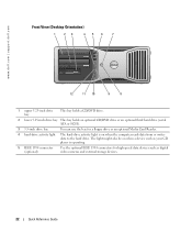
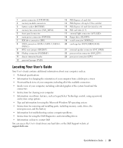
The light might also be on when the computer reads data from or writes data to the hard drive. www.dell.com | support.dell.com Front View (Desktop Orientation) 1 23 456 7 4 3 2 1 12 11 10 9 8 1 upper 5.25-inch drive bay This bay holds a CD/DVD drive. 2 lower 5.25-inch drive ... ATA or SCSI). 3 3.5-inch drive bay You can use the bay for a floppy drive or an optional Media Card Reader. 4 hard-drive activity light The hard-drive activity light is on when a device such as your CD player is operating. 5 IEEE 1394 connector (optional) Use the optional IEEE 1394 connectors for high...
The light might also be on when the computer reads data from or writes data to the hard drive. www.dell.com | support.dell.com Front View (Desktop Orientation) 1 23 456 7 4 3 2 1 12 11 10 9 8 1 upper 5.25-inch drive bay This bay holds a CD/DVD drive. 2 lower 5.25-inch drive ... ATA or SCSI). 3 3.5-inch drive bay You can use the bay for a floppy drive or an optional Media Card Reader. 4 hard-drive activity light The hard-drive activity light is on when a device such as your CD player is operating. 5 IEEE 1394 connector (optional) Use the optional IEEE 1394 connectors for high...
Quick Reference Guide
Page 23
... 23 To exit from a power-saving state, see "Power Management." Use the headphone connector to indicate different states: • No light - The network link light is in the Windows Device Manager. NOTE: The power button can help you troubleshoot a computer problem based on the computer. See "...such as flash memory keys or cameras, or for bootable USB devices (see system setup for more information on page 37 for a description of light codes that typically remain connected, such as a wake device in a normal operating state. • Blinking green - Instead, perform an operating...
... 23 To exit from a power-saving state, see "Power Management." Use the headphone connector to indicate different states: • No light - The network link light is in the Windows Device Manager. NOTE: The power button can help you troubleshoot a computer problem based on the computer. See "...such as flash memory keys or cameras, or for bootable USB devices (see system setup for more information on page 37 for a description of light codes that typically remain connected, such as a wake device in a normal operating state. • Blinking green - Instead, perform an operating...
Quick Reference Guide
Page 25
... network or broadband device, connect one end of the network cable to be in the User's Guide. • Green - Flashes a yellow light when the computer is automatically disabled if the computer detects an installed card containing a parallel connector configured to the network. Quick Reference Guide 25... If you must use the connectors on the card and on the back of network traffic may make this light appear to the network adapter connector on " state. If you have a USB printer, plug it into a USB connector. The computer...
... network or broadband device, connect one end of the network cable to be in the User's Guide. • Green - Flashes a yellow light when the computer is automatically disabled if the computer detects an installed card containing a parallel connector configured to the network. Quick Reference Guide 25... If you must use the connectors on the card and on the back of network traffic may make this light appear to the network adapter connector on " state. If you have a USB printer, plug it into a USB connector. The computer...
Quick Reference Guide
Page 29
... slot 14 PCI-Express x16 up to 150w card slot 15 PCI-Express x8 card slot (wired as x4) 16 PCI card slots (1-3) 17 external light connector (AUX LED) 18 floppy drive (FLOPPY) 19 serial connector (SERIAL2) 20 card cage fan (FAN CARD CAGE) 21 internal speaker connector (INT_SPKR... parts, including memory, cards, drives, the microprocessor, and the battery • Information for troubleshooting various computer problems • Instructions for using the Dell Diagnostics and reinstalling drivers • Information on how to contact Dell You can access the User's Guide from your hard drive or the...
... slot 14 PCI-Express x16 up to 150w card slot 15 PCI-Express x8 card slot (wired as x4) 16 PCI card slots (1-3) 17 external light connector (AUX LED) 18 floppy drive (FLOPPY) 19 serial connector (SERIAL2) 20 card cage fan (FAN CARD CAGE) 21 internal speaker connector (INT_SPKR... parts, including memory, cards, drives, the microprocessor, and the battery • Information for troubleshooting various computer problems • Instructions for using the Dell Diagnostics and reinstalling drivers • Information on how to contact Dell You can access the User's Guide from your hard drive or the...
Quick Reference Guide
Page 31
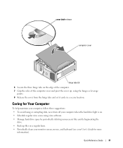
... Computer To help maintain your computer, follow these suggestions: • To avoid losing or corrupting data, never turn off your computer when the hard drive light is on a regular basis. • Periodically clean your monitor screen, mouse, and keyboard (see your User's Guide for more information).
... Computer To help maintain your computer, follow these suggestions: • To avoid losing or corrupting data, never turn off your computer when the hard drive light is on a regular basis. • Periodically clean your monitor screen, mouse, and keyboard (see your User's Guide for more information).
Quick Reference Guide
Page 37
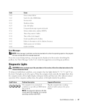
... condition after a short time if the computer is not listed, see the documentation for suggestions on the monitor identifying the problem. The lights can be displayed on resolving any of the procedures in this section, follow the safety instructions in the Product Information Guide. If the...port test failure Failure to decompress code to indicate normal operation. Quick Reference Guide 37 button. After the computer starts, all four lights display solid green briefly and then turn off to shadowed memory Math-coprocessor test failure Cache test failure Error Messages NOTE: If ...
... condition after a short time if the computer is not listed, see the documentation for suggestions on the monitor identifying the problem. The lights can be displayed on resolving any of the procedures in this section, follow the safety instructions in the Product Information Guide. If the...port test failure Failure to decompress code to indicate normal operation. Quick Reference Guide 37 button. After the computer starts, all four lights display solid green briefly and then turn off to shadowed memory Math-coprocessor test failure Cache test failure Error Messages NOTE: If ...
Quick Reference Guide
Page 38
... mode. Memory modules are detected, but a memory failure has occurred. 1 Reseat the memory modules to the operating system. 6 Run the Dell Diagnostics. See page 34 for instructions. 7 If the memory module passes, shut down the computer, remove the memory module, and then repeat... remaining memory modules until new memory modules are not defective. 8 When the defective memory module is in Debug Mode. www.dell.com | support.dell.com Light Pattern Problem Description Suggested Resolution A possible BIOS failure has occurred; the Run the BIOS Recovery utility, wait for Normal Operation....
... mode. Memory modules are detected, but a memory failure has occurred. 1 Reseat the memory modules to the operating system. 6 Run the Dell Diagnostics. See page 34 for instructions. 7 If the memory module passes, shut down the computer, remove the memory module, and then repeat... remaining memory modules until new memory modules are not defective. 8 When the defective memory module is in Debug Mode. www.dell.com | support.dell.com Light Pattern Problem Description Suggested Resolution A possible BIOS failure has occurred; the Run the BIOS Recovery utility, wait for Normal Operation....
Quick Reference Guide
Page 39
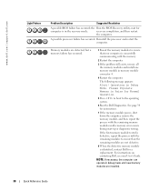
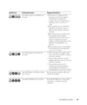
... card that you know works and restart the computer. • If the problem persists or the computer has integrated graphics, contact Dell. A possible floppy or hard drive failure has occurred. A possible USB failure has occurred. Suggested Resolution 1 Determine if a conflict... more information on page 32). 4 If the problem persists, contact Dell. For instructions on contacting Dell, see "Resolving Software and Hardware Incompatibilities" on removing a card, see your User's Guide. Light Pattern Problem Description A possible expansion card failure has occurred. Reseat all...
... card that you know works and restart the computer. • If the problem persists or the computer has integrated graphics, contact Dell. A possible floppy or hard drive failure has occurred. A possible USB failure has occurred. Suggested Resolution 1 Determine if a conflict... more information on page 32). 4 If the problem persists, contact Dell. For instructions on contacting Dell, see "Resolving Software and Hardware Incompatibilities" on removing a card, see your User's Guide. Light Pattern Problem Description A possible expansion card failure has occurred. Reseat all...
Quick Reference Guide
Page 40
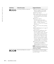
... process with the remaining memory modules until new memory modules are detected. For instructions on contacting Dell, see your User's Guide. www.dell.com | support.dell.com Light Pattern Problem Description No memory modules are installed. Operating in memory module connector 4. 4 Restart ..., and then repeat the process with the remaining modules to ensure that your computer is identified, contact Dell for a replacement.For instructions on contacting Dell, see your User's Guide. 40 Quick Reference Guide Suggested Resolution 1 Reseat the memory modules to the...
... process with the remaining memory modules until new memory modules are detected. For instructions on contacting Dell, see your User's Guide. www.dell.com | support.dell.com Light Pattern Problem Description No memory modules are installed. Operating in memory module connector 4. 4 Restart ..., and then repeat the process with the remaining modules to ensure that your computer is identified, contact Dell for a replacement.For instructions on contacting Dell, see your User's Guide. 40 Quick Reference Guide Suggested Resolution 1 Reseat the memory modules to the...
Quick Reference Guide
Page 41
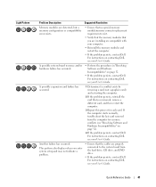
Light Pattern Problem Description Suggested Resolution Memory modules are detected, but a memory configuration or compatibility error exists. • Ensure that no special memory module/memory connector... that you removed, remove a different card, and then restart the computer. 3 Repeat this process for resource conflicts (see "Resolving Software and Hardware Incompatibilities" on contacting Dell, see your User's Guide. Another failure has occurred. Quick Reference Guide 41 A possible expansion card failure has occurred. 1 Determine if a conflict exists by removing a ...
Light Pattern Problem Description Suggested Resolution Memory modules are detected, but a memory configuration or compatibility error exists. • Ensure that no special memory module/memory connector... that you removed, remove a different card, and then restart the computer. 3 Repeat this process for resource conflicts (see "Resolving Software and Hardware Incompatibilities" on contacting Dell, see your User's Guide. Another failure has occurred. Quick Reference Guide 41 A possible expansion card failure has occurred. 1 Determine if a conflict exists by removing a ...
Quick Reference Guide
Page 42
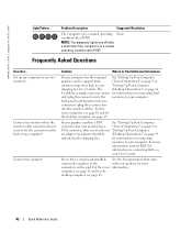
...dell.com | support.dell.com Light Pattern Problem Description Suggested Resolution The computer is in a normal operating condition after POST. Connect my monitor when the monitor cable connector doesn't seem to use two monitors? For the tower information. For the tower computer, see page 10 and for more information, contact Dell.... For more connectors on connecting dual end (plug this connector into the monitor cables). NOTE: The diagnostic lights turn off after POST. back panel) and branches into two connectors (plug these connectors into the monitors to...
...dell.com | support.dell.com Light Pattern Problem Description Suggested Resolution The computer is in a normal operating condition after POST. Connect my monitor when the monitor cable connector doesn't seem to use two monitors? For the tower information. For the tower computer, see page 10 and for more information, contact Dell.... For more connectors on connecting dual end (plug this connector into the monitor cables). NOTE: The diagnostic lights turn off after POST. back panel) and branches into two connectors (plug these connectors into the monitors to...
Quick Reference Guide
Page 45
...25 power, 21, 24 serial, 26 sound, 26 USB, 20, 23, 26 D Dell support site, 7 Dell Diagnostics, 34 Dell Premier Support website, 6-7 diagnostic lights, 37 diagnostics beep codes, 36 Dell, 34 Drivers and Utilities CD, 5 lights, 20, 23, 37 documentation device, 5 online, 7 Product Information Guide, 6 Quick... 6 drivers ResourceCD, 5 Drivers and Utilities CD, 5 E error messages beep codes, 36 diagnostic lights, 37 H hard drive activity light, 19-20, 22-23 hardware beep codes, 36 conflicts, 32 Dell Diagnostics, 34 Hardware Troubleshooter, 32 headphone connector, 20, 23 Help and Support Center, 7 I ...
...25 power, 21, 24 serial, 26 sound, 26 USB, 20, 23, 26 D Dell support site, 7 Dell Diagnostics, 34 Dell Premier Support website, 6-7 diagnostic lights, 37 diagnostics beep codes, 36 Dell, 34 Drivers and Utilities CD, 5 lights, 20, 23, 37 documentation device, 5 online, 7 Product Information Guide, 6 Quick... 6 drivers ResourceCD, 5 Drivers and Utilities CD, 5 E error messages beep codes, 36 diagnostic lights, 37 H hard drive activity light, 19-20, 22-23 hardware beep codes, 36 conflicts, 32 Dell Diagnostics, 34 Hardware Troubleshooter, 32 headphone connector, 20, 23 Help and Support Center, 7 I ...
Quick Reference Guide
Page 46
... P power button, 20, 23 connector, 21, 24 light, 20, 23 problems beep codes, 36 conflicts, 32 Dell Diagnostics, 34 diagnostic lights, 37 restore to previous state, 32 R reinstalling Drivers and Utilities CD, 5 ResourceCD, 5 ResourceCD Dell Diagnostics, 34 N network connector, 25 O Operating System ...software conflicts, 32 sound connectors line-in, 26 line-out, 26 system board, 28 System Restore, 32 T troubleshooting conflicts, 32 Dell Diagnostics, 34 diagnostic lights, 37 Hardware Troubleshooter, 32 Help and Support Center, 7 restore to previous state, 32 U USB connector, 26 connectors, 20, ...
... P power button, 20, 23 connector, 21, 24 light, 20, 23 problems beep codes, 36 conflicts, 32 Dell Diagnostics, 34 diagnostic lights, 37 restore to previous state, 32 R reinstalling Drivers and Utilities CD, 5 ResourceCD, 5 ResourceCD Dell Diagnostics, 34 N network connector, 25 O Operating System ...software conflicts, 32 sound connectors line-in, 26 line-out, 26 system board, 28 System Restore, 32 T troubleshooting conflicts, 32 Dell Diagnostics, 34 diagnostic lights, 37 Hardware Troubleshooter, 32 Help and Support Center, 7 restore to previous state, 32 U USB connector, 26 connectors, 20, ...


