User's Guide
Page 9
Safety Instructions Safety First-For You and Your Computer Before you remove the computer cover, perform the following steps in your online Dell™ documentation or otherwise provided to you. NOTICE: Do not attempt to avoid bending any telephone or telecommunication lines from their power sources...on the chassis, such as a microprocessor chip by its edges, not by the manufacturer. Hold a component such as the metal around the card-slot openings at the back of cable, press in on a card. if you connect a cable, make sure both connectors are disconnecting this type of the computer,...
Safety Instructions Safety First-For You and Your Computer Before you remove the computer cover, perform the following steps in your online Dell™ documentation or otherwise provided to you. NOTICE: Do not attempt to avoid bending any telephone or telecommunication lines from their power sources...on the chassis, such as a microprocessor chip by its edges, not by the manufacturer. Hold a component such as the metal around the card-slot openings at the back of cable, press in on a card. if you connect a cable, make sure both connectors are disconnecting this type of the computer,...

User's Guide
Page 18
Then perform an orderly shutdown of indicator codes and operations. controls the system's AC input power. www.dell.com | support.dell.com Front View of the Desktop Chassis reset button power indicator power button hard-drive access indicator diskette-drive access indicator NOTE: ... or Windows NT®. 18 Abo u t You r C o mp u t er If your computer is not responding, you push this button, save and close all open files and application programs if possible to reboot the system. For more information, see "Recover From a Program That Is Not Responding" and "Restart a Computer That...
Then perform an orderly shutdown of indicator codes and operations. controls the system's AC input power. www.dell.com | support.dell.com Front View of the Desktop Chassis reset button power indicator power button hard-drive access indicator diskette-drive access indicator NOTE: ... or Windows NT®. 18 Abo u t You r C o mp u t er If your computer is not responding, you push this button, save and close all open files and application programs if possible to reboot the system. For more information, see "Recover From a Program That Is Not Responding" and "Restart a Computer That...

User's Guide
Page 36
... this setting, a DMI event is generated, the setting changes to select Reset, and then choose Enabled, Enabled-Silent, or Disabled. • Enabled-Silent - www.dell.com | support.dell.com Security The computer provides the following message appears during the boot routine at the next system start -up . • Disabled - The Chassis Intrusion... chassis: • Chassis intrusion detection • Security cable slot and padlock ring Chassis Intrusion Detection The chassis intrusion monitor can detect whether the chassis is opened.
... this setting, a DMI event is generated, the setting changes to select Reset, and then choose Enabled, Enabled-Silent, or Disabled. • Enabled-Silent - www.dell.com | support.dell.com Security The computer provides the following message appears during the boot routine at the next system start -up . • Disabled - The Chassis Intrusion... chassis: • Chassis intrusion detection • Security cable slot and padlock ring Chassis Intrusion Detection The chassis intrusion monitor can detect whether the chassis is opened.

User's Guide
Page 51
...Turning off the computer by the Auto Power On option in a batch file to turn off the system from the Dell support website. AutoShutdown The Dell AutoShutdown utility lets you perform an orderly system shutdown and then turn off your computer after successfully closing the OS. All... installed the system utilities. The functions of this is installed and running under Windows NT, open the Control Panel and double-click Services. Auto Power On The Dell Auto Power On utility is intended only for more information. Advanced Features 51 See "Finding Information and Assistance" ...
...Turning off the computer by the Auto Power On option in a batch file to turn off the system from the Dell support website. AutoShutdown The Dell AutoShutdown utility lets you perform an orderly system shutdown and then turn off your computer after successfully closing the OS. All... installed the system utilities. The functions of this is installed and running under Windows NT, open the Control Panel and double-click Services. Auto Power On The Dell Auto Power On utility is intended only for more information. Advanced Features 51 See "Finding Information and Assistance" ...

User's Guide
Page 68
...equal force applied at each end of the socket. 1 Press the securing clips at each end of the socket outward simultaneously until they snap open (see the following figure). 2 Lift the module away from the socket. NOTICE: To avoid damage to the memory module, press the ...of the socket outward until the module pops out slightly from the system board, verify that the standby power indicator on the computer. www.dell.com | support.dell.com Removing a Memory Module NOTICE: Before disconnecting a peripheral from the system or removing a component from the socket (see "System Board ...
...equal force applied at each end of the socket. 1 Press the securing clips at each end of the socket outward simultaneously until they snap open (see the following figure). 2 Lift the module away from the socket. NOTICE: To avoid damage to the memory module, press the ...of the socket outward until the module pops out slightly from the system board, verify that the standby power indicator on the computer. www.dell.com | support.dell.com Removing a Memory Module NOTICE: Before disconnecting a peripheral from the system or removing a component from the socket (see "System Board ...
User's Guide
Page 101
... connectors on the system back panel (see "Back-Panel Connectors and Indicators"). Cover was previously removed. 9 If you need a filler bracket, contact Dell and order part number 81808. b Connect the network cable to be displayed at the next system start-up: ALERT! The brackets also keep dust ... corners, and ease it out of its connector. 6 If you are removing the card permanently, install a filler bracket in the empty card-slot opening, using the screw you removed the AGP brace, replace it. 8 Replace the computer cover, reconnect the computer and peripherals to their electrical outlets,...
... connectors on the system back panel (see "Back-Panel Connectors and Indicators"). Cover was previously removed. 9 If you need a filler bracket, contact Dell and order part number 81808. b Connect the network cable to be displayed at the next system start-up: ALERT! The brackets also keep dust ... corners, and ease it out of its connector. 6 If you are removing the card permanently, install a filler bracket in the empty card-slot opening, using the screw you removed the AGP brace, replace it. 8 Replace the computer cover, reconnect the computer and peripherals to their electrical outlets,...

User's Guide
Page 133
...the following steps. Go to their electrical outlets, and turn them on. No. Contact Dell for technical assistance. S o lv ing Pr o ble m s 133 CAUTION: Before you perform the following methods: - Contact Dell for technical assistance. Yes. Using Microsoft Windows or Windows NT®, insert a diskette ...the boot routine? Go to clean drive heads with a swab. • Try a different diskette in the Dell Diagnostics. Using MS-DOS®, insert a diskette into the drive, open My Computer from their electrical outlets, wait at the prompt, and press . - If the problem still ...
...the following steps. Go to their electrical outlets, and turn them on. No. Contact Dell for technical assistance. S o lv ing Pr o ble m s 133 CAUTION: Before you perform the following methods: - Contact Dell for technical assistance. Yes. Using Microsoft Windows or Windows NT®, insert a diskette ...the boot routine? Go to clean drive heads with a swab. • Try a different diskette in the Dell Diagnostics. Using MS-DOS®, insert a diskette into the drive, open My Computer from their electrical outlets, wait at the prompt, and press . - If the problem still ...

User's Guide
Page 134
...Problems Basic Checks: • If you perform this procedure, see "Safety First- For Microsoft Windows, run the error-checking utility by opening the property sheet of the affected volume(s) and clicking Check Now in the Error-checking section of the following steps. CAUTION: Before you... hear an unfamiliar scraping or grinding sound when a drive is accessed, there could be a hardware malfunction. Contact Dell for technical assistance. • When you turn on the computer, you perform the following methods: - Is the drive operating properly? 134 ...
...Problems Basic Checks: • If you perform this procedure, see "Safety First- For Microsoft Windows, run the error-checking utility by opening the property sheet of the affected volume(s) and clicking Check Now in the Error-checking section of the following steps. CAUTION: Before you... hear an unfamiliar scraping or grinding sound when a drive is accessed, there could be a hardware malfunction. Contact Dell for technical assistance. • When you turn on the computer, you perform the following methods: - Is the drive operating properly? 134 ...
User's Guide
Page 135
... . • For Microsoft Windows, run the ScanDisk utility by clicking the Start button, pointing to step 3. 3 Run the appropriate test group in the Dell Diagnostics: • For an integrated drive electronics (IDE) hard drive, run the IDE Devices device group. • For a small computer system interface ...(SCSI) hard drive, run the error-checking utility by opening the property sheet of the affected volume(s) and clicking Check Now in the Error-checking section of the diagnostics tests fail? No. Go to...
... . • For Microsoft Windows, run the ScanDisk utility by clicking the Start button, pointing to step 3. 3 Run the appropriate test group in the Dell Diagnostics: • For an integrated drive electronics (IDE) hard drive, run the IDE Devices device group. • For a small computer system interface ...(SCSI) hard drive, run the error-checking utility by opening the property sheet of the affected volume(s) and clicking Check Now in the Error-checking section of the diagnostics tests fail? No. Go to...

User's Guide
Page 144
...applications for no apparent reason. • Nothing displays on the printer. • Mouse pointer hangs and will not move or moves in the Dell Diagnostics. • Reseat the memory modules. 144 So lv ing Pr o ble m s To resolve hardware conflicts: • Ensure that the...the hardware manufacturer. • See your operating system documentation. Basic Checks: • If an insufficient memory message appears, save and close any open application programs not in use. • Consider installing additional system memory. • Run the System Memory test in a stuttering fashion. •...
...applications for no apparent reason. • Nothing displays on the printer. • Mouse pointer hangs and will not move or moves in the Dell Diagnostics. • Reseat the memory modules. 144 So lv ing Pr o ble m s To resolve hardware conflicts: • Ensure that the...the hardware manufacturer. • See your operating system documentation. Basic Checks: • If an insufficient memory message appears, save and close any open application programs not in use. • Consider installing additional system memory. • Run the System Memory test in a stuttering fashion. •...
User's Guide
Page 151
... appears followed by the installation program. NOTE: If you want to restore it after running the Dell Diagnostics. 5 Press to exit system setup and save your changes. If the Welcome Dell System Owner screen opens, click Next to continue. 6 Select the number for the first time on the NIC S... o lv ing Pr o ble m s 151 Dell Diagnostics: Loads the Dell Diagnostics that run system tests • Option 3 - A numbered list...
... appears followed by the installation program. NOTE: If you want to restore it after running the Dell Diagnostics. 5 Press to exit system setup and save your changes. If the Welcome Dell System Owner screen opens, click Next to continue. 6 Select the number for the first time on the NIC S... o lv ing Pr o ble m s 151 Dell Diagnostics: Loads the Dell Diagnostics that run system tests • Option 3 - A numbered list...

User's Guide
Page 173
... leave portions of their setup information behind, even though you install a Plug and Play card in a Plug and Play computer, the computer automatically selects an open IRQ line if any are available. Rebooting your system can change the address of one of the available IRQ lines. For example, if a network expansion...
... leave portions of their setup information behind, even though you install a Plug and Play card in a Plug and Play computer, the computer automatically selects an open IRQ line if any are available. Rebooting your system can change the address of one of the available IRQ lines. For example, if a network expansion...
User's Guide
Page 178
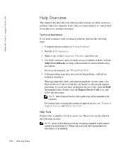
...directly to the proper support personnel. Help Tools Dell provides a number of online services available at Dell's website (http://www.dell.com) for technical or customer assistance. www.dell.com | support.dell.com Help Overview This chapter describes the tools Dell provides to help with your computer. For ...on using the technical support service, see "World Wide Web." 5 If the preceding steps have an Express Service Code, open the Dell Accessories folder, double-click the Express Service Code icon, and follow the directions. For more information, see "Technical Support Service...
...directly to the proper support personnel. Help Tools Dell provides a number of online services available at Dell's website (http://www.dell.com) for technical or customer assistance. www.dell.com | support.dell.com Help Overview This chapter describes the tools Dell provides to help with your computer. For ...on using the technical support service, see "World Wide Web." 5 If the preceding steps have an Express Service Code, open the Dell Accessories folder, double-click the Express Service Code icon, and follow the directions. For more information, see "Technical Support Service...

User's Guide
Page 179
... system information to support.dell.com page opens. World Wide Web The Internet is your most of the services described in as user: anonymous, and use your e-mail address as your password. • Electronic Support Service support@us.dell.com apsupport@dell.com (for Asian/Pacific countries only) support.euro.dell.com (for Europe only...
... system information to support.dell.com page opens. World Wide Web The Internet is your most of the services described in as user: anonymous, and use your e-mail address as your password. • Electronic Support Service support@us.dell.com apsupport@dell.com (for Asian/Pacific countries only) support.euro.dell.com (for Europe only...

Service Manual
Page 41
... the front-panel insert for the chassis drive bay you want to press the sides of the insert until it snaps free of the bay opening, and then press the ring tabs over the posts. Panel Ins ert s 41
... the front-panel insert for the chassis drive bay you want to press the sides of the insert until it snaps free of the bay opening, and then press the ring tabs over the posts. Panel Ins ert s 41

Service Manual
Page 42
See "Removing Front-Panel Inserts (Mini Tower Chassis)." 42 Fr ont- Panel Inserts www.dell.com | support.dell.com Removing Front-Panel Inserts (Mini Tower Chassis) front panel posts (2) ring tabs (2) front-panel insert Replacing Front-Panel Inserts (Mini Tower Chassis) Position the two ring-tabs over the posts on the inside of the bay opening, and then press the ring tabs over the posts.
See "Removing Front-Panel Inserts (Mini Tower Chassis)." 42 Fr ont- Panel Inserts www.dell.com | support.dell.com Removing Front-Panel Inserts (Mini Tower Chassis) front panel posts (2) ring tabs (2) front-panel insert Replacing Front-Panel Inserts (Mini Tower Chassis) Position the two ring-tabs over the posts on the inside of the bay opening, and then press the ring tabs over the posts.

Service Manual
Page 59
Removing a Memory Module securing clips (2) Replacing a Memory Module 1 Install the memory module: a Press the securing clips at the ends of the socket outward until the securing clips snap into the socket until they snap open (see the following figure). c Press the memory module straight down into place at each end of the module. b Align the slots on the bottom of the memory module with the two ridges inside the socket. S ys tem Memor y 59
Removing a Memory Module securing clips (2) Replacing a Memory Module 1 Install the memory module: a Press the securing clips at the ends of the socket outward until the securing clips snap into the socket until they snap open (see the following figure). c Press the memory module straight down into place at each end of the module. b Align the slots on the bottom of the memory module with the two ridges inside the socket. S ys tem Memor y 59

Service Manual
Page 104
Install all screws on the expansion card's bracket. 7 If you are removing the card permanently, install a filler bracket in the empty card-slot opening, using the screw you removed the AGP brace, replace it. 104 Ex p a n s io n C a r d s See the User's Guide for information ...out of the system. NOTE: Installing filler brackets over empty card-slot openings is necessary to maintain Federal Communications Commission (FCC) certification of your computer. 8 If you removed in step 5. www.dell.com | support.dell.com Removing an Expansion Card screw bracket expansion card card edge connector ...
Install all screws on the expansion card's bracket. 7 If you are removing the card permanently, install a filler bracket in the empty card-slot opening, using the screw you removed the AGP brace, replace it. 104 Ex p a n s io n C a r d s See the User's Guide for information ...out of the system. NOTE: Installing filler brackets over empty card-slot openings is necessary to maintain Federal Communications Commission (FCC) certification of your computer. 8 If you removed in step 5. www.dell.com | support.dell.com Removing an Expansion Card screw bracket expansion card card edge connector ...
Service Manual
Page 120
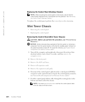
... or removing a component from the system board, verify that the control-panel alignment hole is positioned over the guide pin. NOTE: You must open the drive door and free the control-panel cable from the control-panel (PANEL) connector on the system board. To locate this procedure, see...Label." 1 Turn off . To replace the control panel, perform the removal procedure in the bottom and front wall of the chassis. www.dell.com | support.dell.com Replacing the Control Panel (Desktop Chassis) NOTE: When mounting the control panel on the chassis, ensure that the standby power indicator on the...
... or removing a component from the system board, verify that the control-panel alignment hole is positioned over the guide pin. NOTE: You must open the drive door and free the control-panel cable from the control-panel (PANEL) connector on the system board. To locate this procedure, see...Label." 1 Turn off . To replace the control panel, perform the removal procedure in the bottom and front wall of the chassis. www.dell.com | support.dell.com Replacing the Control Panel (Desktop Chassis) NOTE: When mounting the control panel on the chassis, ensure that the standby power indicator on the...

Service Manual
Page 126
... the hard-drive thermal sensor cable from the control panel connector (THERMAL). To locate this connector, see the following figure). www.dell.com | support.dell.com Mini Tower Chassis • Removing the hard-drive thermal sensor • Replacing the hard-drive thermal sensor Removing the Hard-... see "System Board Components" or "Interior Service Label." 1 Turn off . To locate this indicator, see "Precautionary Measures." NOTE: You must open the drive door to feed the thermal sensor cable through the routing holes in the front wall of the chassis (see "Control Panel Components." 8...
... the hard-drive thermal sensor cable from the control panel connector (THERMAL). To locate this connector, see the following figure). www.dell.com | support.dell.com Mini Tower Chassis • Removing the hard-drive thermal sensor • Replacing the hard-drive thermal sensor Removing the Hard-... see "System Board Components" or "Interior Service Label." 1 Turn off . To locate this indicator, see "Precautionary Measures." NOTE: You must open the drive door to feed the thermal sensor cable through the routing holes in the front wall of the chassis (see "Control Panel Components." 8...


