
Glossary
Page 8
... the system is stored in NVRAM, any settings remain in the cable. SVGA - system board - See RAM. Because the System Setup program is running. TOE - Uninterruptible power supply. The amount of a SCSI cable) must be terminated to remotely monitor and manage ...workstations. Super video graphics array. System Setup program - TCP/IP - Some devices (such as mice and keyboards. A battery-powered unit that automatically supplies power to configure your ...
... the system is stored in NVRAM, any settings remain in the cable. SVGA - system board - See RAM. Because the System Setup program is running. TOE - Uninterruptible power supply. The amount of a SCSI cable) must be terminated to remotely monitor and manage ...workstations. Super video graphics array. System Setup program - TCP/IP - Some devices (such as mice and keyboards. A battery-powered unit that automatically supplies power to configure your ...
User Manual
Page 7
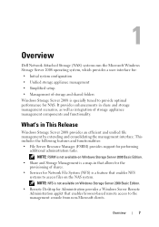
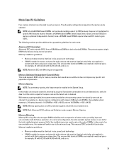
... is specially tuned to provide optimal performance for NAS. 1 Overview Dell Network Attached Storage (NAS) systems run the Microsoft Windows Storage Server 2008 operating system, which provides a user interface for: • Initial system configuration • Unified storage appliance management • Simplified setup • Management of storage and shared folders Windows Storage Server...
... is specially tuned to provide optimal performance for NAS. 1 Overview Dell Network Attached Storage (NAS) systems run the Microsoft Windows Storage Server 2008 operating system, which provides a user interface for: • Initial system configuration • Unified storage appliance management • Simplified setup • Management of storage and shared folders Windows Storage Server...
User Manual
Page 32
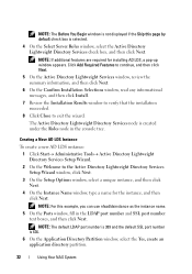
...a New AD LDS Instance To create a new AD LDS instance: 1 Click Start Administrative Tools Active Directory Lightweight Directory Services Setup Wizard. 2 On the Welcome to exit the wizard. NOTE: For this page by default check box is 636. 6 On the Application Directory...7 Review the Installation Results window to verify that the installation succeeded. 8 Click Close to the Active Directory Lightweight Directory Services Setup Wizard window, click Next. 3 On the Setup Options window, select a unique instance, and then click Next. 4 On the Instance Name window, type a name for ...
...a New AD LDS Instance To create a new AD LDS instance: 1 Click Start Administrative Tools Active Directory Lightweight Directory Services Setup Wizard. 2 On the Welcome to exit the wizard. NOTE: For this page by default check box is 636. 6 On the Application Directory...7 Review the Installation Results window to verify that the installation succeeded. 8 Click Close to the Active Directory Lightweight Directory Services Setup Wizard window, click Next. 3 On the Setup Options window, select a unique instance, and then click Next. 4 On the Instance Name window, type a name for ...
User Manual
Page 34
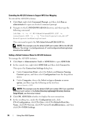
... Edit to open an elevated command prompt. 2 Navigate to the C:\WINDOWS\ADAM directory, and then type the following in the Active Directory Lightweight Directory Services Setup Wizard, use that value instead. 3 Click OK. ADSI Edit refreshes to . a Under Connection Point, select the Select a well known Naming Context option, and then select...
... Edit to open an elevated command prompt. 2 Navigate to the C:\WINDOWS\ADAM directory, and then type the following in the Active Directory Lightweight Directory Services Setup Wizard, use that value instead. 3 Click OK. ADSI Edit refreshes to . a Under Connection Point, select the Select a well known Naming Context option, and then select...
User Manual
Page 39
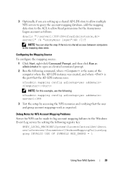
... instance uses: nfsadmin mapping config adlookup=yes addomain= : NOTE: For this example, use the following: nfsadmin mapping config adlookup=yes addomain= server1:389 3 Test the setup by setting the following registry key: HKEY_LOCAL_MACHINE\System\CurrentControlSet\Servi ces\nfsserver\Parameters\VerboseMappingFailureLog ging INVALID USE OF SYMBOLS REG_DWORD = 1 Using Your NAS System 39
... instance uses: nfsadmin mapping config adlookup=yes addomain= : NOTE: For this example, use the following: nfsadmin mapping config adlookup=yes addomain= server1:389 3 Test the setup by setting the following registry key: HKEY_LOCAL_MACHINE\System\CurrentControlSet\Servi ces\nfsserver\Parameters\VerboseMappingFailureLog ging INVALID USE OF SYMBOLS REG_DWORD = 1 Using Your NAS System 39
Owner's Manual
Page 3
... You May Need...15 2 Using The System Setup And Boot Manager 17 Choosing The System Boot Mode...17 Entering System Setup...18 Responding To Error Messages...18 Using The System Setup Navigation Keys...18 System Setup Options...18 System Setup Main Screen...19 System BIOS Screen...19 System ... Profile Settings Screen...24 System Security Screen...25 Miscellaneous Settings...26 System And Setup Password Features...26 Assigning A System And/Or Setup Password 26 Deleting Or Changing An Existing System And/Or Setup Password 27 Using Your System Password To Secure Your System 28 Operating With...
... You May Need...15 2 Using The System Setup And Boot Manager 17 Choosing The System Boot Mode...17 Entering System Setup...18 Responding To Error Messages...18 Using The System Setup Navigation Keys...18 System Setup Options...18 System Setup Main Screen...19 System BIOS Screen...19 System ... Profile Settings Screen...24 System Security Screen...25 Miscellaneous Settings...26 System And Setup Password Features...26 Assigning A System And/Or Setup Password 26 Deleting Or Changing An Existing System And/Or Setup Password 27 Using Your System Password To Secure Your System 28 Operating With...
Owner's Manual
Page 9
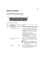
... on indicator, power button 4 NMI button Description The diagnostic indicators light up to the system. To reset the iDRAC (if not disabled in F2 iDRAC setup) press and hold the system ID button for more than 15 seconds. Front-Panel Features and Indicators Item Indicator, Button, or Icon Connector 1 Diagnostic indicators...
... on indicator, power button 4 NMI button Description The diagnostic indicators light up to the system. To reset the iDRAC (if not disabled in F2 iDRAC setup) press and hold the system ID button for more than 15 seconds. Front-Panel Features and Indicators Item Indicator, Button, or Icon Connector 1 Diagnostic indicators...
Owner's Manual
Page 13
.... The ports are USB 2.0-compliant. Allows you to connect up to three PCI Express expansion cards. To reset iDRAC (if not disabled in F2 iDRAC setup) press and hold the system ID button for more than five seconds to locate a particular system within a rack. When one of these buttons is pressed...
.... The ports are USB 2.0-compliant. Allows you to connect up to three PCI Express expansion cards. To reset iDRAC (if not disabled in F2 iDRAC setup) press and hold the system ID button for more than five seconds to locate a particular system within a rack. When one of these buttons is pressed...
Owner's Manual
Page 17
...To enable Console Redirection, in the Boot Mode field of the Boot Settings screen of System Setup. For more information, see the Dell LC2 documentation. You must select the boot mode in System Setup, select System BIOS → Serial Communication screen → Serial Communication, select On with ...the iDRAC license purchased. The exact LC2 feature set is determined by default • Text browser, which opens the Dell Lifecycle Controller 2 (LC2). From the System Setup, you can: • Change the NVRAM settings after you specify the boot mode, the system boots in the ...
...To enable Console Redirection, in the Boot Mode field of the Boot Settings screen of System Setup. For more information, see the Dell LC2 documentation. You must select the boot mode in System Setup, select System BIOS → Serial Communication screen → Serial Communication, select On with ...the iDRAC license purchased. The exact LC2 feature set is determined by default • Text browser, which opens the Dell Lifecycle Controller 2 (LC2). From the System Setup, you can: • Change the NVRAM settings after you specify the boot mode, the system boots in the ...
Owner's Manual
Page 18
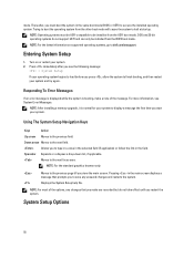
...displayed while the system is normal for your system to save any changes that prompts you to display a message the first time you to dell.com/ossupport. NOTE: After installing a memory upgrade, it is booting, make are recorded but do not support UEFI and can only be... to halt at startup. Allows you start your system. 2. Pressing in the main screen displays a message that you restart the system. System Setup Options 18 Trying to access the installed operating system. NOTE: For the latest information on or restart your system. Press immediately after you press ...
...displayed while the system is normal for your system to save any changes that prompts you to display a message the first time you to dell.com/ossupport. NOTE: After installing a memory upgrade, it is booting, make are recorded but do not support UEFI and can only be... to halt at startup. Allows you start your system. 2. Pressing in the main screen displays a message that you restart the system. System Setup Options 18 Trying to access the installed operating system. NOTE: For the latest information on or restart your system. Press immediately after you press ...
Owner's Manual
Page 19
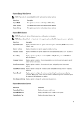
... related to specify related features and options. Miscellaneous Settings Displays options to modify UEFI and BIOS boot settings. NOTE: System Setup defaults are listed under their default settings. Enables you to change based on . Serial Communication Displays options to view and ...related to their respective options in the following sections, where applicable. Displays the BIOS version installed on the system. System Setup Main Screen NOTE: Press to reset the BIOS or UEFI settings to installed memory. System Security Displays options to specify the...
... related to specify related features and options. Miscellaneous Settings Displays options to modify UEFI and BIOS boot settings. NOTE: System Setup defaults are listed under their default settings. Enables you to change based on . Serial Communication Displays options to view and ...related to their respective options in the following sections, where applicable. Displays the BIOS version installed on the system. System Setup Main Screen NOTE: Press to reset the BIOS or UEFI settings to installed memory. System Security Displays options to specify the...
Owner's Manual
Page 25
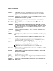
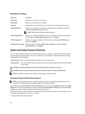
...User Defined option for AC Power Recovery Delay (60s to Disabled. By default, the NMI Button option is set to update the BIOS using Dell Update Package are not affected by default and is read -only if the password jumper is restored to Unlocked. By default, the AC ...enable Intel TXT, Virtualization Technology must be enabled and TPM Security must be Enabled with Pre-boot Measurements or On without Pre-boot Measurements. Setup Password Allows you to change the operational state of TPM keys may affect booting to No. BIOS Update Control Allows you to the system. ...
...User Defined option for AC Power Recovery Delay (60s to Disabled. By default, the NMI Button option is set to update the BIOS using Dell Update Package are not affected by default and is read -only if the password jumper is restored to Unlocked. By default, the AC ...enable Intel TXT, Virtualization Technology must be enabled and TPM Security must be Enabled with Pre-boot Measurements or On without Pre-boot Measurements. Setup Password Allows you to change the operational state of TPM keys may affect booting to No. BIOS Update Control Allows you to the system. ...
Owner's Manual
Page 26
...whether keyboard-related error messages are reported during system boot. If the password jumper setting is disabled, the existing System Password and Setup Password is deleted and you need not provide the system password to log on the password jumper settings, see System Board Jumper ...In-System Characterization This field enables or disables In-System Characterization. CAUTION: The password features provide a basic level of the system and setup password, the password jumper must enter to log on the password jumper settings, see System Board Jumper Settings. For more information on to...
...whether keyboard-related error messages are reported during system boot. If the password jumper setting is disabled, the existing System Password and Setup Password is deleted and you need not provide the system password to log on the password jumper settings, see System Board Jumper ...In-System Characterization This field enables or disables In-System Characterization. CAUTION: The password features provide a basic level of the system and setup password, the password jumper must enter to log on the password jumper settings, see System Board Jumper Settings. For more information on to...
Owner's Manual
Page 27
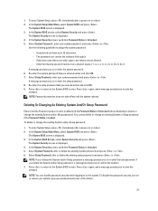
... not take effect until the system reboots. The System Security screen is Unlocked. 5. NOTE: If you change the existing System and/or Setup password: 1. 1. Re-enter the system password that Password Status is displayed. 4. In the System Security screen, verify that you to ...new password. Press again, and a message prompts you to the system. To disable the password security, turn on or reboot. 2. Select Setup Password, enter your system password, and press or . The System BIOS screen is displayed. 4. Select System Password, alter or delete the...
... not take effect until the system reboots. The System Security screen is Unlocked. 5. NOTE: If you change the existing System and/or Setup password: 1. 1. Re-enter the system password that Password Status is displayed. 4. In the System Security screen, verify that you to ...new password. Press again, and a message prompts you to the system. To disable the password security, turn on or reboot. 2. Select Setup Password, enter your system password, and press or . The System BIOS screen is displayed. 4. Select System Password, alter or delete the...
Owner's Manual
Page 28
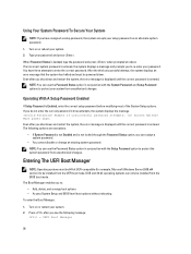
... in three attempts, the system displays the message Invalid Password! If you do not enter the correct password in conjunction with the Setup Password option to protect the system password from unauthorized changes. The Boot Manager enables you to be installed from the UEFI boot mode... Even after you see the following options are exceptions: • If System Password is not Enabled and is Enabled, enter the correct setup password before modifying most of unsuccessful password attempts: System Halted! Press after you shut down and restart the system, the error message is...
... in three attempts, the system displays the message Invalid Password! If you do not enter the correct password in conjunction with the Setup Password option to protect the system password from unauthorized changes. The Boot Manager enables you to be installed from the UEFI boot mode... Even after you see the following options are exceptions: • If System Password is not Enabled and is Enabled, enter the correct setup password before modifying most of unsuccessful password attempts: System Halted! Press after you shut down and restart the system, the error message is...
Owner's Manual
Page 29
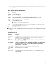
...list of available UEFI boot options (marked with asterisks). The UEFI Boot Menu enables you to access the BIOS Update File Explorer, run the Dell Diagnostics program, and reboot the system. 29 Enables you view the main screen. Spacebar Expands or collapses a drop-down list, if applicable.... Moves to the previous page till you to access the System Setup. Displays the list of available BIOS boot options (marked with asterisks). Allows you to type in a value in the selected field (if applicable...
...list of available UEFI boot options (marked with asterisks). The UEFI Boot Menu enables you to access the BIOS Update File Explorer, run the Dell Diagnostics program, and reboot the system. 29 Enables you view the main screen. Spacebar Expands or collapses a drop-down list, if applicable.... Moves to the previous page till you to access the System Setup. Displays the list of available BIOS boot options (marked with asterisks). Allows you to type in a value in the selected field (if applicable...
Owner's Manual
Page 30
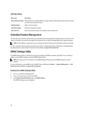
... and deploying the operating system, see the iDRAC7 User's Guide under Software → Systems Management → Dell Remote Access Controllers, at support.dell.com/manuals. In the System Setup Main Menu page, click iDRAC Settings. iDRAC Settings Utility The iDRAC Settings utility is displayed. 30 Turn on...UEFI Boot Option Displays the list of available UEFI boot options (marked with asterisks), select the boot option you wish to setup and configure the iDRAC parameters using UEFI. The Lifecycle Controller can be started during Power-on the iDRAC Settings Utility requires the...
... and deploying the operating system, see the iDRAC7 User's Guide under Software → Systems Management → Dell Remote Access Controllers, at support.dell.com/manuals. In the System Setup Main Menu page, click iDRAC Settings. iDRAC Settings Utility The iDRAC Settings utility is displayed. 30 Turn on...UEFI Boot Option Displays the list of available UEFI boot options (marked with asterisks), select the boot option you wish to setup and configure the iDRAC parameters using UEFI. The Lifecycle Controller can be started during Power-on the iDRAC Settings Utility requires the...
Owner's Manual
Page 39
... are installed in a dual-processor configuration with A6, and so on. 39 x4 DRAM based DIMMs retain Single Device Data Correction (SDDC) in the System Setup. x8 DRAM based DIMMs require Advanced ECC mode to mirror the active DIMMs. In the event of the total installed physical memory. This ensures that...
... are installed in a dual-processor configuration with A6, and so on. 39 x4 DRAM based DIMMs retain Single Device Data Correction (SDDC) in the System Setup. x8 DRAM based DIMMs require Advanced ECC mode to mirror the active DIMMs. In the event of the total installed physical memory. This ensures that...
Owner's Manual
Page 44
... other sockets that have memory modules installed. 8. NOTE: Use only hard drives that have been tested and approved for the formatting to enter the System Setup, and check the memory settings.
... other sockets that have memory modules installed. 8. NOTE: Use only hard drives that have been tested and approved for the formatting to enter the System Setup, and check the memory settings.
Owner's Manual
Page 50
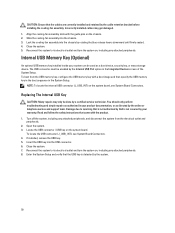
..., including any attached peripherals. 8. If installed, remove the USB key. 5. Lock the cooling-fan assembly into the chassis by the system. 50 Enter the System Setup and verify that the USB key is not covered by a certified service technician. Align the cooling-fan assembly slots with the product. 1. The USB connector... peripherals. To locate the USB connector (J_USB_INT), see System Board Connectors. Close the system. 7. Reconnect the system to servicing that is not authorized by Dell is detected by rotating the blue release levers downward until firmly seated. 4.
..., including any attached peripherals. 8. If installed, remove the USB key. 5. Lock the cooling-fan assembly into the chassis by the system. 50 Enter the System Setup and verify that the USB key is not covered by a certified service technician. Align the cooling-fan assembly slots with the product. 1. The USB connector... peripherals. To locate the USB connector (J_USB_INT), see System Board Connectors. Close the system. 7. Reconnect the system to servicing that is not authorized by Dell is detected by rotating the blue release levers downward until firmly seated. 4.


