
Glossary
Page 1
Dell™ Glossary NOTE: For additional information on storage terminology, visit the Storage Networking Industry Association's website at www.snia.org and click on a regular basis. A - AC - Advanced Configuration and Power Interface. The temperature of a program or data file. The primary ...or room where the system is used to the system. Baseboard management controller. Your system contains an expansion bus that includes power supplies and fans. Celsius. Common Information Model describes the management information utilized by an administrator, for interchange of CIM data with...
Dell™ Glossary NOTE: For additional information on storage terminology, visit the Storage Networking Industry Association's website at www.snia.org and click on a regular basis. A - AC - Advanced Configuration and Power Interface. The temperature of a program or data file. The primary ...or room where the system is used to the system. Baseboard management controller. Your system contains an expansion bus that includes power supplies and fans. Celsius. Common Information Model describes the management information utilized by an administrator, for interchange of CIM data with...

Glossary
Page 8
...with greater resolution and color display capabilities than previous standards. See RAM. Transmission Control Protocol/Internet Protocol. A battery-powered unit that automatically supplies power to describe a system that tells a system what hardware is running. USB - USB memory key - See memory ...main circuit board, the system board usually contains most of an electrical failure. Symmetric multiprocessing. SMP - Uninterruptible power supply. USB devices can be terminated to prevent reflections and spurious signals in the event of your system's integral ...
...with greater resolution and color display capabilities than previous standards. See RAM. Transmission Control Protocol/Internet Protocol. A battery-powered unit that automatically supplies power to describe a system that tells a system what hardware is running. USB - USB memory key - See memory ...main circuit board, the system board usually contains most of an electrical failure. Symmetric multiprocessing. SMP - Uninterruptible power supply. USB devices can be terminated to prevent reflections and spurious signals in the event of your system's integral ...

Glossary
Page 48
Unregistered DDR3 UPS - Volts alternating current VDC - Zero insertion force 48 Uninterruptible power supply USB - Windows Management Instrumentation。CIM ZIF - Super video graphics array VGA と SVGA TCP/IP - Volt direct current VGA - Simple Network Management Protocol SVGA - ...
Unregistered DDR3 UPS - Volts alternating current VDC - Zero insertion force 48 Uninterruptible power supply USB - Windows Management Instrumentation。CIM ZIF - Super video graphics array VGA と SVGA TCP/IP - Volt direct current VGA - Simple Network Management Protocol SVGA - ...

Glossary
Page 58
TCP/IP TCP/IP Offload Engine U-DIMM DDR3 Unregistered(Unbuffered) DDR3 Memory Module UPS Uninterruptible Power Supply USB Universal Serial Bus USB USB USB USB V - 볼트 (Volt VAC Volt Alternating Current VDC ...Watt WH Watt-Hour WMI - Windows Management Instrumentation 은 CIM ZIF Zero Insertion Force provider CIM management station managed system) 은 Dell OpenManage™ Server Administrator x x y x z 58 SVGA Super Video Graphics Array VGA 와 SVGA TCP/IP Transmission Control Protocol/Internet Protocol TOE ...
TCP/IP TCP/IP Offload Engine U-DIMM DDR3 Unregistered(Unbuffered) DDR3 Memory Module UPS Uninterruptible Power Supply USB Universal Serial Bus USB USB USB USB V - 볼트 (Volt VAC Volt Alternating Current VDC ...Watt WH Watt-Hour WMI - Windows Management Instrumentation 은 CIM ZIF Zero Insertion Force provider CIM management station managed system) 은 Dell OpenManage™ Server Administrator x x y x z 58 SVGA Super Video Graphics Array VGA 와 SVGA TCP/IP Transmission Control Protocol/Internet Protocol TOE ...

Getting Started Guide
Page 4
Connecting The Power Cable(s) Figure 3. Securing The Power Cable(s) Figure 4. Plug the other end of the power cable(s) into a grounded electrical outlet or a separate power source such as shown in the illustration, and attach to the monitor. Connecting the Power Cable(s) Connect the system's power cable(s) to the system and, if a monitor is used, connect the monitor's power cable to the cable strap. Securing the Power Cable(s) Bend the system power cable(s), as an uninterruptible power supply (UPS) or a power distribution unit (PDU). 4
Connecting The Power Cable(s) Figure 3. Securing The Power Cable(s) Figure 4. Plug the other end of the power cable(s) into a grounded electrical outlet or a separate power source such as shown in the illustration, and attach to the monitor. Connecting the Power Cable(s) Connect the system's power cable(s) to the system and, if a monitor is used, connect the monitor's power cable to the cable strap. Securing the Power Cable(s) Bend the system power cable(s), as an uninterruptible power supply (UPS) or a power distribution unit (PDU). 4
Getting Started Guide
Page 6
...power supply unit) 50/60 Hz (AC power supply unit) 12-6.5 A (X2) (per 1100 W AC power supply unit) 10-5 A (X2) (per 750 W AC power supply unit) 6.5-3 A (X2) (per 495 W AC power supply unit) 32 A (X2) (per 1100 W DC power supply unit) NOTE: (X #), # = Maximum number of the official Mexican standards (NOM): Importer: Dell Inc. Dell...purchased with your system. This document is provided on support.dell.com/manuals and read the updates first because they often supersede information in compliance with the requirements of power supplies per system. 6 Lomas Altas 11950 México, D.F....
...power supply unit) 50/60 Hz (AC power supply unit) 12-6.5 A (X2) (per 1100 W AC power supply unit) 10-5 A (X2) (per 750 W AC power supply unit) 6.5-3 A (X2) (per 495 W AC power supply unit) 32 A (X2) (per 1100 W DC power supply unit) NOTE: (X #), # = Maximum number of the official Mexican standards (NOM): Importer: Dell Inc. Dell...purchased with your system. This document is provided on support.dell.com/manuals and read the updates first because they often supersede information in compliance with the requirements of power supplies per system. 6 Lomas Altas 11950 México, D.F....

Getting Started Guide
Page 7
... listing of the specifications for specific system configurations, see dell.com/environmental_datasheets. Technical Specifications NOTE: The following specifications are only those required by law to ship with a phase to phase voltage not exceeding 230 V. 100-240 V AC, autoranging, 50/60 Hz DC Power Supply (per power supply) (when available) Wattage Heat dissipation NOTE: Heat dissipation...
... listing of the specifications for specific system configurations, see dell.com/environmental_datasheets. Technical Specifications NOTE: The following specifications are only those required by law to ship with a phase to phase voltage not exceeding 230 V. 100-240 V AC, autoranging, 50/60 Hz DC Power Supply (per power supply) (when available) Wattage Heat dissipation NOTE: Heat dissipation...

Owner's Manual
Page 5
... Card...71 Processors...71 Removing A Processor...72 Installing A Processor...75 Power Supplies...76 Hot Spare Feature...77 Removing An AC Power Supply...77 Installing An AC Power Supply...78 Wiring Instructions For A DC Power Supply...79 Removing A DC Power Supply...81 Installing A DC Power Supply...82 Removing The Power Supply Blank...83 Installing The Power Supply Blank...83 System Battery...83 Replacing The System Battery...83...
... Card...71 Processors...71 Removing A Processor...72 Installing A Processor...75 Power Supplies...76 Hot Spare Feature...77 Removing An AC Power Supply...77 Installing An AC Power Supply...78 Wiring Instructions For A DC Power Supply...79 Removing A DC Power Supply...81 Installing A DC Power Supply...82 Removing The Power Supply Blank...83 Installing The Power Supply Blank...83 System Battery...83 Replacing The System Battery...83...

Owner's Manual
Page 6
... A NIC...98 Troubleshooting A Wet System...98 Troubleshooting A Damaged System...99 Troubleshooting The System Battery...100 Troubleshooting Power Supplies...100 Troubleshooting Cooling Problems...100 Troubleshooting Cooling Fans...101 Troubleshooting System Memory...101 Troubleshooting An Internal USB Key...102... A Storage Controller...104 Troubleshooting Expansion Cards...105 Troubleshooting Processors...106 5 Using System Diagnostics...107 Dell Online Diagnostics...107 Dell Embedded System Diagnostics...107 When To Use The Embedded System Diagnostics 107 Running The Embedded System ...
... A NIC...98 Troubleshooting A Wet System...98 Troubleshooting A Damaged System...99 Troubleshooting The System Battery...100 Troubleshooting Power Supplies...100 Troubleshooting Cooling Problems...100 Troubleshooting Cooling Fans...101 Troubleshooting System Memory...101 Troubleshooting An Internal USB Key...102... A Storage Controller...104 Troubleshooting Expansion Cards...105 Troubleshooting Processors...106 5 Using System Diagnostics...107 Dell Online Diagnostics...107 Dell Embedded System Diagnostics...107 When To Use The Embedded System Diagnostics 107 Running The Embedded System ...
Owner's Manual
Page 9
... system status indicator on indicator lights when the system power is pressed again. The power button controls the power supply output to display error status. Used to troubleshoot software and device driver errors when running certain operating systems. This button can be pressed using the power button causes the system to perform a graceful shutdown before...
... system status indicator on indicator lights when the system power is pressed again. The power button controls the power supply output to display error status. Used to troubleshoot software and device driver errors when running certain operating systems. This button can be pressed using the power button causes the system to perform a graceful shutdown before...
Owner's Manual
Page 11
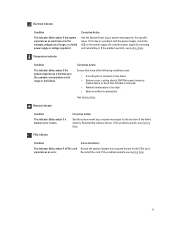
...bracket is removed. • Ambient temperature is too high. • External airflow is due to a problem with the power supply, check the LED on the power supply. If it . See Getting Help. Memory indicator Condition The indicator blinks amber if a memory error occurs. Re-install ...Condition The indicator blinks amber if the system experiences a thermal error (for example, a temperature out of range, or a failed power supply or voltage regulator). Electrical indicator Condition The indicator blinks amber if the system experiences an electrical error (for example, voltage out of...
...bracket is removed. • Ambient temperature is too high. • External airflow is due to a problem with the power supply, check the LED on the power supply. If it . See Getting Help. Memory indicator Condition The indicator blinks amber if a memory error occurs. Re-install ...Condition The indicator blinks amber if the system experiences a thermal error (for example, a temperature out of range, or a failed power supply or voltage regulator). Electrical indicator Condition The indicator blinks amber if the system experiences an electrical error (for example, voltage out of...
Owner's Manual
Page 13
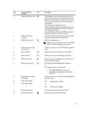
... to the system. 6 Video connector Allows you to connect a VGA display to the system. 7 USB connectors (2) 8 Ethernet connectors (4) 9 PCIe expansion card slots full height (3) 10 Power supply (PSU1) 11 Power supply (PSU2) Allows you to connect up to locate a particular system within a rack.
... to the system. 6 Video connector Allows you to connect a VGA display to the system. 7 USB connectors (2) 8 Ethernet connectors (4) 9 PCIe expansion card slots full height (3) 10 Power supply (PSU1) 11 Power supply (PSU2) Allows you to connect up to locate a particular system within a rack.

Owner's Manual
Page 14
... Indicator 1. Activity indicator is blinking green Network data is present or whether a power fault has occurred. Power Indicator Codes Each AC power supply has an illuminated translucent handle and each DC power supply (when available) has an LED that serves as an indicator to a valid network at less than its... Link and activity indicators are off The NIC is connected to show whether power is being sent or received. Link indicator is amber The NIC is connected to the network. AC power supply status indicator/handle 14 Link indicator is green The NIC is not connected ...
... Indicator 1. Activity indicator is blinking green Network data is present or whether a power fault has occurred. Power Indicator Codes Each AC power supply has an illuminated translucent handle and each DC power supply (when available) has an LED that serves as an indicator to a valid network at less than its... Link and activity indicators are off The NIC is connected to show whether power is being sent or received. Link indicator is amber The NIC is connected to the network. AC power supply status indicator/handle 14 Link indicator is green The NIC is not connected ...

Owner's Manual
Page 15
... or vice versa, you must be included within this indicates that the power supply is mismatched with the power supply. To change from a High Output configuration to the power supply and that the power supply is operational. When two identical power supplies receive different input voltages, they must power down the system. Other Information You May Need WARNING: See the safety...
... or vice versa, you must be included within this indicates that the power supply is mismatched with the power supply. To change from a High Output configuration to the power supply and that the power supply is operational. When two identical power supplies receive different input voltages, they must power down the system. Other Information You May Need WARNING: See the safety...

Owner's Manual
Page 31
... and pull the bezel away from the front panel. 4. Lift the release latch next to ground Following tools are required for assembling cables for a DC power supply unit (PSU), when available: • AMP 90871-1 hand-crimping tool or equivalent • Wire-stripper pliers capable of the bezel away from the system. Removing...
... and pull the bezel away from the front panel. 4. Lift the release latch next to ground Following tools are required for assembling cables for a DC power supply unit (PSU), when available: • AMP 90871-1 hand-crimping tool or equivalent • Wire-stripper pliers capable of the bezel away from the system. Removing...

Owner's Manual
Page 76
...release lever near the lock icon until it is redundant (1 + 1). Using a clean lint-free cloth, remove the thermal grease from both power supplies to verify that the processor information matches the new system configuration. 20. Place the heat sink on the socket, as applicable. Reconnect your ...socket. Press to the center of the topside of the thermal grease in position. 12. When only one power supply is installed, the power supply configuration is supplied to the system equally from the heat sink. Run the system diagnostics to maximize efficiency. Align the processor ...
...release lever near the lock icon until it is redundant (1 + 1). Using a clean lint-free cloth, remove the thermal grease from both power supplies to verify that the processor information matches the new system configuration. 20. Place the heat sink on the socket, as applicable. Reconnect your ...socket. Press to the center of the topside of the thermal grease in position. 12. When only one power supply is installed, the power supply configuration is supplied to the system equally from the heat sink. Run the system diagnostics to maximize efficiency. Align the processor ...
Owner's Manual
Page 77
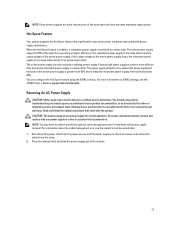
... a certified service technician. Disconnect the power cable from the power source and the power supply you intend to a sleep state. The active power supply supports 100% of the active power supply drops, the redundant power supply in the sleep state monitors output voltage of the active power supply. The power supply defaults are used, they must be done by Dell is switched to remove and...
... a certified service technician. Disconnect the power cable from the power source and the power supply you intend to a sleep state. The active power supply supports 100% of the active power supply drops, the redundant power supply in the sleep state monitors output voltage of the active power supply. The power supply defaults are used, they must be done by Dell is switched to remove and...

Owner's Manual
Page 78
.... CAUTION: When connecting the power cable, secure the cable with the product. 1. Removing and Installing an AC Power Supply 1. Damage due to signify that both the power supplies are the same type and have the same maximum output power. connector 2. power supply 3. Read and follow the safety instructions that is not authorized by Dell is fully seated and the...
.... CAUTION: When connecting the power cable, secure the cable with the product. 1. Removing and Installing an AC Power Supply 1. Damage due to signify that both the power supplies are the same type and have the same maximum output power. connector 2. power supply 3. Read and follow the safety instructions that is not authorized by Dell is fully seated and the...

Owner's Manual
Page 79
...8226; Current consumption: 32 A (maximum) Kit Contents • Dell part number 6RYJ9 terminal block or equivalent (1) • #6-32 nut equipped with the product. 1. Wiring Instructions For A DC Power Supply Your system supports up to DC power or installing grounds yourself. Ensure that is electrically isolated from the end... overcurrent protection rated 50 A for source and return. Do not attempt connecting to two -(48-60) V DC power supplies (when available). Damage due to servicing that is not authorized by Dell is efficiently secured to servicing that is not authorized by...
...8226; Current consumption: 32 A (maximum) Kit Contents • Dell part number 6RYJ9 terminal block or equivalent (1) • #6-32 nut equipped with the product. 1. Wiring Instructions For A DC Power Supply Your system supports up to DC power or installing grounds yourself. Ensure that is electrically isolated from the end... overcurrent protection rated 50 A for source and return. Do not attempt connecting to two -(48-60) V DC power supplies (when available). Damage due to servicing that is not authorized by Dell is efficiently secured to servicing that is not authorized by...

Owner's Manual
Page 80
...Dell is not covered by your warranty. Figure 39. locking washer 4. spring washer 5. #6-32 nut Assembling The DC Input Power Wires WARNING: For equipment using a #6-32 nut equipped with the rubber cap before inserting the mating connector into the power supply. 3. Insert the copper ends into the power supply... on the back of the mating connector using a #2 Phillips screwdriver. WARNING: Reversing polarity when connecting DC power wires can permanently damage the power supply or the system. 2. Insert the mating connector into the mating connectors and tighten the captive screws at the...
...Dell is not covered by your warranty. Figure 39. locking washer 4. spring washer 5. #6-32 nut Assembling The DC Input Power Wires WARNING: For equipment using a #6-32 nut equipped with the rubber cap before inserting the mating connector into the power supply. 3. Insert the copper ends into the power supply... on the back of the mating connector using a #2 Phillips screwdriver. WARNING: Reversing polarity when connecting DC power wires can permanently damage the power supply or the system. 2. Insert the mating connector into the mating connectors and tighten the captive screws at the...


