
User Manual
Page 7
... for the provisioning of shares. • Services for Network File System (NFS) is not available on the NAS system. 1 Overview Dell Network Attached Storage (NAS) systems run the Microsoft Windows Storage Server 2008 operating system, which provides a user interface for: • ...Initial system configuration • Unified storage appliance management • Simplified setup • Management of storage and shared folders Windows Storage Server 2008 is specially tuned to the management console from non-Microsoft clients....
... for the provisioning of shares. • Services for Network File System (NFS) is not available on the NAS system. 1 Overview Dell Network Attached Storage (NAS) systems run the Microsoft Windows Storage Server 2008 operating system, which provides a user interface for: • ...Initial system configuration • Unified storage appliance management • Simplified setup • Management of storage and shared folders Windows Storage Server 2008 is specially tuned to the management console from non-Microsoft clients....

User Manual
Page 32
...New AD LDS Instance To create a new AD LDS instance: 1 Click Start Administrative Tools Active Directory Lightweight Directory Services Setup Wizard. 2 On the Welcome to exit the wizard. NOTE: For this page by default check box is selected. 4 On the Select.... 7 Review the Installation Results window to verify that the installation succeeded. 8 Click Close to the Active Directory Lightweight Directory Services Setup Wizard window, click Next. 3 On the Setup Options window, select a unique instance, and then click Next. 4 On the Instance Name window, type a name for installing ...
...New AD LDS Instance To create a new AD LDS instance: 1 Click Start Administrative Tools Active Directory Lightweight Directory Services Setup Wizard. 2 On the Welcome to exit the wizard. NOTE: For this page by default check box is selected. 4 On the Select.... 7 Review the Installation Results window to verify that the installation succeeded. 8 Click Close to the Active Directory Lightweight Directory Services Setup Wizard window, click Next. 3 On the Setup Options window, select a unique instance, and then click Next. 4 On the Instance Name window, type a name for installing ...

User Manual
Page 34
..., right-click ADSI Edit and then click Connect to the C:\WINDOWS\ADAM directory, and then type the following in the Active Directory Lightweight Directory Services Setup Wizard, use that value instead. 3 Click OK. The strings "cn=Configuration,dc=X" and #configurationNamingContext should not be modified. ADSI Edit refreshes to display the new...
..., right-click ADSI Edit and then click Connect to the C:\WINDOWS\ADAM directory, and then type the following in the Active Directory Lightweight Directory Services Setup Wizard, use that value instead. 3 Click OK. The strings "cn=Configuration,dc=X" and #configurationNamingContext should not be modified. ADSI Edit refreshes to display the new...

User Manual
Page 39
... instance uses: nfsadmin mapping config adlookup=yes addomain= : NOTE: For this example, use the following: nfsadmin mapping config adlookup=yes addomain= server1:389 3 Test the setup by setting the following command, where is the name of the computer where the AD LDS instance was created, and where is no shared access...
... instance uses: nfsadmin mapping config adlookup=yes addomain= : NOTE: For this example, use the following: nfsadmin mapping config adlookup=yes addomain= server1:389 3 Test the setup by setting the following command, where is the name of the computer where the AD LDS instance was created, and where is no shared access...

Hardware Owner's Manual
Page 4
... and UEFI Boot Manager 57 Choosing the System Boot Mode 57 Entering the System Setup Program 58 System Setup Options 59 Entering the UEFI Boot Manager 69 System and Setup Password Features 72 Embedded System Management 75 Baseboard Management Controller Configuration 76 iDRAC Configuration Utility 77 3 Installing System Components 79 Recommended Tools 79...
... and UEFI Boot Manager 57 Choosing the System Boot Mode 57 Entering the System Setup Program 58 System Setup Options 59 Entering the UEFI Boot Manager 69 System and Setup Password Features 72 Embedded System Management 75 Baseboard Management Controller Configuration 76 iDRAC Configuration Utility 77 3 Installing System Components 79 Recommended Tools 79...

Hardware Owner's Manual
Page 9
...) or iDRAC Configuration Utility, which opens the Unified Server Configurator. Enters the utility to the system. Keystroke Description Enters the System Setup program. Enters System Services, which allows access to the system event log (SEL) and configuration of remote access to configure NIC ... utilities such as embedded system diagnostics. The Unified Server Configurator allows you to system features during startup. See "Using the System Setup Program and UEFI Boot Manager" on page 57. For more information, see the documentation for your SAS RAID card. Starts PXE...
...) or iDRAC Configuration Utility, which opens the Unified Server Configurator. Enters the utility to the system. Keystroke Description Enters the System Setup program. Enters System Services, which allows access to the system event log (SEL) and configuration of remote access to configure NIC ... utilities such as embedded system diagnostics. The Unified Server Configurator allows you to system features during startup. See "Using the System Setup Program and UEFI Boot Manager" on page 57. For more information, see the documentation for your SAS RAID card. Starts PXE...

Hardware Owner's Manual
Page 14
Setup Menu Option Description BMC or DRAC Select DHCP or Static IP to select the up arrow until the Home icon is selected, the available fields ... to view domain addresses. To navigate to the Home screen from another menu, continue to configure the network NOTE: If an iDRAC6 Express mode. Select Setup DNS to system, the BMC option is installed on page 23 for a list of messages in this format. See "LCD Status Messages (Optional)" on the...
Setup Menu Option Description BMC or DRAC Select DHCP or Static IP to select the up arrow until the Home icon is selected, the available fields ... to view domain addresses. To navigate to the Home screen from another menu, continue to configure the network NOTE: If an iDRAC6 Express mode. Select Setup DNS to system, the BMC option is installed on page 23 for a list of messages in this format. See "LCD Status Messages (Optional)" on the...

Hardware Owner's Manual
Page 15
... 14). Addresses include DNS (Primary and Secondary), card is NOTE: BMC IP supports only IPv4 addresses. Temperature Displays the temperature of the Setup menu (see "Setup Menu" on the Gateway, IP, and Subnet (IPv6 does not have Subnet). About Your System 15 The display format can be configured ... the BMC IP option is installed on page 14). Name Displays the name of the system in the "Set home" submenu of the Setup menu (see "Setup Menu" on the system, the MAC option displays the MAC addresses for DRAC, iSCSIn, or NETn. Power Displays the power output of ...
... 14). Addresses include DNS (Primary and Secondary), card is NOTE: BMC IP supports only IPv4 addresses. Temperature Displays the temperature of the Setup menu (see "Setup Menu" on the Gateway, IP, and Subnet (IPv6 does not have Subnet). About Your System 15 The display format can be configured ... the BMC IP option is installed on page 14). Name Displays the name of the system in the "Set home" submenu of the Setup menu (see "Setup Menu" on the system, the MAC option displays the MAC addresses for DRAC, iSCSIn, or NETn. Power Displays the power output of ...

Hardware Owner's Manual
Page 19
... amber blinking Indicator Code The NIC is not connected to a valid network link at 10/100 Mbps. NIC Indicator Codes Figure 1-5. See "Using the System Setup Program and UEFI Boot Manager" on the network. Guidelines for the attached device has been installed on your system, use the System... Setup program. Turn on any external devices before attaching a new external device. The NIC is being sent or received. Network data is connected to a valid link ...
... amber blinking Indicator Code The NIC is not connected to a valid network link at 10/100 Mbps. NIC Indicator Codes Figure 1-5. See "Using the System Setup Program and UEFI Boot Manager" on the network. Guidelines for the attached device has been installed on your system, use the System... Setup program. Turn on any external devices before attaching a new external device. The NIC is being sent or received. Network data is connected to a valid link ...

Hardware Owner's Manual
Page 23
...the code, then see the systems management software documentation. You can be defined by descriptive text. See "Using the following conditions: System Setup Program • The system is off and active errors are displayed. LCD Status Messages (Optional) The system's control panel LCD provides status... failure Contact events. The LCD lights blue to indicate a normal operating condition, and lights amber to events recorded in the System Setup program. The LCD messages refer to indicate an error condition. About Your System 23 The LCD scrolls a message that This message ...
...the code, then see the systems management software documentation. You can be defined by descriptive text. See "Using the following conditions: System Setup Program • The system is off and active errors are displayed. LCD Status Messages (Optional) The system's control panel LCD provides status... failure Contact events. The LCD lights blue to indicate a normal operating condition, and lights amber to events recorded in the System Setup program. The LCD messages refer to indicate an error condition. About Your System 23 The LCD scrolls a message that This message ...

Hardware Owner's Manual
Page 38
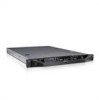
... supports Advanced ECC Memory Mode. iDRAC6 not responding. The Advanced ECC option was enabled in a configuration that the memory modules are installed in the system setup program, but is not responding to reboot. 38 About Your System Reconfigure the memory modules for possible causes. For memory configuration information, see "Troubleshooting System...
... supports Advanced ECC Memory Mode. iDRAC6 not responding. The Advanced ECC option was enabled in a configuration that the memory modules are installed in the system setup program, but is not responding to reboot. 38 About Your System Reconfigure the memory modules for possible causes. For memory configuration information, see "Troubleshooting System...

Hardware Owner's Manual
Page 40
... use the components. If Energy Smart power supplies are not supported with High Output power supplies to the previous configuration. See system setup program, but "Troubleshooting System the current configuration Memory" on page 57. Continuing system boot accepts the risk that system may not ... then the replaced component(s) are installed, replace them with this power supply. Alert! If the system boots without warning. the System Setup Program and UEFI Boot Manager" on page 154. An error caused the system to Check other system reboot. Check PSU and system ...
... use the components. If Energy Smart power supplies are not supported with High Output power supplies to the previous configuration. See system setup program, but "Troubleshooting System the current configuration Memory" on page 57. Continuing system boot accepts the risk that system may not ... then the replaced component(s) are installed, replace them with this power supply. Alert! If the system boots without warning. the System Setup Program and UEFI Boot Manager" on page 154. An error caused the system to Check other system reboot. Check PSU and system ...

Hardware Owner's Manual
Page 41
attempt failed. Caution! Please run SETUP NVRAM_CLR jumper is in manufacturing Reboot to take the system mode. See Figure 6-1 for possible causes. Restart the system and re-enter the BIOS settings. ..., intentionally set to the default position (pins 3 and 5). Move the NVRAM_CLR jumper to minimum frequency. Install memory modules for normal operation. See "Using the System Setup Program and UEFI Boot Manager" on system board. CPU x installed with no memory. out of manufacturing mode. Retry the BIOS update. NVRAM_CLR jumper is installed...
attempt failed. Caution! Please run SETUP NVRAM_CLR jumper is in manufacturing Reboot to take the system mode. See Figure 6-1 for possible causes. Restart the system and re-enter the BIOS settings. ..., intentionally set to the default position (pins 3 and 5). Move the NVRAM_CLR jumper to minimum frequency. Install memory modules for normal operation. See "Using the System Setup Program and UEFI Boot Manager" on system board. CPU x installed with no memory. out of manufacturing mode. Retry the BIOS update. NVRAM_CLR jumper is installed...

Hardware Owner's Manual
Page 42
... logical processors, and power rating. See "Processors" on page 57. System halted Current boot mode is non- Use the system setup program to UEFI. available. See "Using the UEFI. System Setup Program and UEFI Boot Manager" on page 122. memory modules. System Messages (continued) Message CPUs with different logical processors detected! CPUs...
... logical processors, and power rating. See "Processors" on page 57. System halted Current boot mode is non- Use the system setup program to UEFI. available. See "Using the UEFI. System Setup Program and UEFI Boot Manager" on page 122. memory modules. System Messages (continued) Message CPUs with different logical processors detected! CPUs...

Hardware Owner's Manual
Page 43
...See "Getting Help" on page 148. page 177. Run the System Setup program and review the current settings. About Your System 43 Invalid configuration information please run SETUP program. See "Using the System Setup Program and UEFI Boot Manager" on a dual-processor system. Table ... is indicated, see "Troubleshooting a NIC" on page 149. Management Shared NIC= Check the system management software or the System Setup program for each CPU should match. Invalid memory configuration on page 57. Defective mouse or keyboard. An invalid system configuration caused ...
...See "Getting Help" on page 148. page 177. Run the System Setup program and review the current settings. About Your System 43 Invalid configuration information please run SETUP program. See "Using the System Setup Program and UEFI Boot Manager" on a dual-processor system. Table ... is indicated, see "Troubleshooting a NIC" on page 149. Management Shared NIC= Check the system management software or the System Setup program for each CPU should match. Invalid memory configuration on page 57. Defective mouse or keyboard. An invalid system configuration caused ...

Hardware Owner's Manual
Page 44
... dedicated storage controller slot. Local keyboard may be reduced Invalid memory Ensure that the memory modules are disabled. See "Entering the System Setup Program" on page 115. The system will run but with the specified memory module disabled. See "General Memory Module Installation Guidelines" ...Overcurrent detected at the See "Getting Help" on page 113. page 177. If operating locally, power cycle the system and enter system setup program to enable the USB port(s). The USB ports are installed in a valid configuration. Manufacturing mode detected System is in the system ...
... dedicated storage controller slot. Local keyboard may be reduced Invalid memory Ensure that the memory modules are disabled. See "Entering the System Setup Program" on page 115. The system will run but with the specified memory module disabled. See "General Memory Module Installation Guidelines" ...Overcurrent detected at the See "Getting Help" on page 113. page 177. If operating locally, power cycle the system and enter system setup program to enable the USB port(s). The USB ports are installed in a valid configuration. Manufacturing mode detected System is in the system ...
Hardware Owner's Manual
Page 46
...devices. See your hard drive. See "Using the System Setup Program and UEFI Boot Manager" on page 57 for information on page 57. PCIe Training Faulty or improperly Error: Expected installed PCIe card in System Setup program, or no bootable USB key installed. Reseat the... PCIe card in the System Setup program. Check the hard drive configuration settings in the specified slot number. See "Troubleshooting ...
...devices. See your hard drive. See "Using the System Setup Program and UEFI Boot Manager" on page 57 for information on page 57. PCIe Training Faulty or improperly Error: Expected installed PCIe card in System Setup program, or no bootable USB key installed. Reseat the... PCIe card in the System Setup program. Check the hard drive configuration settings in the specified slot number. See "Troubleshooting ...

Hardware Owner's Manual
Page 49
... memory modules do not match in a valid configuration. Thermal sensor not detected on page 152. Memory" on page 57. faulty system SETUP program battery. Ensure that the memory modules are installed in size, number of ranks, or number of data lanes. See "System the... specified memory slot. About Your System 49 The following DIMMs should match in module. please run settings; See "Using the System Setup Program and UEFI Boot Manager" on page 115. Causes Corrective Actions Invalid memory configuration. See "General Memory Module Installation Guidelines" on page...
... memory modules do not match in a valid configuration. Thermal sensor not detected on page 152. Memory" on page 57. faulty system SETUP program battery. Ensure that the memory modules are installed in size, number of ranks, or number of data lanes. See "System the... specified memory slot. About Your System 49 The following DIMMs should match in module. please run settings; See "Using the System Setup Program and UEFI Boot Manager" on page 115. Causes Corrective Actions Invalid memory configuration. See "General Memory Module Installation Guidelines" on page...

Hardware Owner's Manual
Page 52
... in the specified memory mode to Optimized or Sparing in "Troubleshooting Your System" on page 115. reboot. Table 1-3. during the error. section in the BIOS setup screen. System Messages (continued) Message Causes Corrective Actions Unsupported memory configuration. DIMM's installed in the following slot are not available when in mirror mode: x,x,x The... is not optimal for Advanced Advanced ECC Memory ECC Memory Mode. Mode, or change the memory mode to Optimized slots are mismatched in the BIOS setup screen. Unused memory detected.
... in the specified memory mode to Optimized or Sparing in "Troubleshooting Your System" on page 115. reboot. Table 1-3. during the error. section in the BIOS setup screen. System Messages (continued) Message Causes Corrective Actions Unsupported memory configuration. DIMM's installed in the following slot are not available when in mirror mode: x,x,x The... is not optimal for Advanced Advanced ECC Memory ECC Memory Mode. Mode, or change the memory mode to Optimized slots are mismatched in the BIOS setup screen. Unused memory detected.

Hardware Owner's Manual
Page 57
... the boot mode, the system boots in the Boot Mode field of the Boot Settings screen of the System Setup program. Using the System Setup Program and UEFI Boot Manager 57 From the System Setup program, you can only be installed from the other boot mode will cause the system to halt immediately... also enables you to specify the boot mode for more information on page 63. Using the System Setup Program and UEFI Boot Manager The System Setup program is the BIOS program that enables you to manage your operating system: • BIOS boot mode (the default) is the standard BIOS-level boot ...
... the boot mode, the system boots in the Boot Mode field of the Boot Settings screen of the System Setup program. Using the System Setup Program and UEFI Boot Manager 57 From the System Setup program, you can only be installed from the other boot mode will cause the system to halt immediately... also enables you to specify the boot mode for more information on page 63. Using the System Setup Program and UEFI Boot Manager The System Setup program is the BIOS program that enables you to manage your operating system: • BIOS boot mode (the default) is the standard BIOS-level boot ...


