View
Page 4
All rights reserved. Reproduction in any proprietary interest in this document to refer to either potential damage to hardware or loss of Dell Inc. Other trademarks and trade names may be used in this text: Dell and the DELL logo are trademarks of data and tells you make better use of Dell Inc. NOTICE: A NOTICE indicates either the entities claiming the...
All rights reserved. Reproduction in any proprietary interest in this document to refer to either potential damage to hardware or loss of Dell Inc. Other trademarks and trade names may be used in this text: Dell and the DELL logo are trademarks of data and tells you make better use of Dell Inc. NOTICE: A NOTICE indicates either the entities claiming the...

View
Page 5
... physical disks • Configuration and monitoring via the MD Storage Manager software • Four sensors for monitoring ambient temperatures • Battery backup unit (BBU) to power the RAID controller system memory (cache) in case of a power outage • Over-temperature shutdown capability • Support for a wide range of servers (See your system include: • Efficient rack-mount designed storage system • Capacity for 15 1-inch, hot-plug, 3.0-Gbps, serial-attached SCSI (SAS...
... physical disks • Configuration and monitoring via the MD Storage Manager software • Four sensors for monitoring ambient temperatures • Battery backup unit (BBU) to power the RAID controller system memory (cache) in case of a power outage • Over-temperature shutdown capability • Support for a wide range of servers (See your system include: • Efficient rack-mount designed storage system • Capacity for 15 1-inch, hot-plug, 3.0-Gbps, serial-attached SCSI (SAS...

View
Page 6
... provide last-minute updates to set up your system for more information. Installation and Configuration CAUTION: Before performing the following procedure, read and follow the safety instructions and important regulatory information in your Hardware Owner's Manual. This service may be offered in this document or as expected, see www.dell.com/training for the first time. 4 Getting Started With Your System Obtaining Technical Assistance If you...
... provide last-minute updates to set up your system for more information. Installation and Configuration CAUTION: Before performing the following procedure, read and follow the safety instructions and important regulatory information in your Hardware Owner's Manual. This service may be offered in this document or as expected, see www.dell.com/training for the first time. 4 Getting Started With Your System Obtaining Technical Assistance If you...

View
Page 7
Installing the Rails and System in a Rack Once you need them later. Keep all shipping materials in case you have read the "Safety Instructions" located in the rack installation documentation for instructions on installing your system in the rack. See your rack installation documentation for your system and identify each item. Unpacking the System Unpack your system, install the rails and the system in a rack. Getting Started With Your System 5
Installing the Rails and System in a Rack Once you need them later. Keep all shipping materials in case you have read the "Safety Instructions" located in the rack installation documentation for instructions on installing your system in the rack. See your rack installation documentation for your system and identify each item. Unpacking the System Unpack your system, install the rails and the system in a rack. Getting Started With Your System 5
View
Page 8
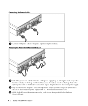
... the top of the loop and the middle clasp to the bracket's cable clasp. Connecting the Power Cables Connect both power cables to the instructions provided in the Hardware Owner's Manual. 6 Getting Started With Your System Attach the system power cable to the vertical middle of the power cables into a grounded electrical outlet or a separate power source such as an uninterruptible power supply (UPS) or a power distribution unit (PDU).
... the top of the loop and the middle clasp to the bracket's cable clasp. Connecting the Power Cables Connect both power cables to the instructions provided in the Hardware Owner's Manual. 6 Getting Started With Your System Attach the system power cable to the vertical middle of the power cables into a grounded electrical outlet or a separate power source such as an uninterruptible power supply (UPS) or a power distribution unit (PDU).
View
Page 9
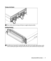
Getting Started With Your System 7 Turning on the System Power on the system by inserting the right edge of the bezel to the system until the bezel snaps into the right front loop on both power supply/cooling fan modules. Installing the Bezel Install the bezel (optional) by turning on the system, and then pressing the left edge of the bezel into place.
Getting Started With Your System 7 Turning on the System Power on the system by inserting the right edge of the bezel to the system until the bezel snaps into the right front loop on both power supply/cooling fan modules. Installing the Bezel Install the bezel (optional) by turning on the system, and then pressing the left edge of the bezel into place.

View
Page 10
... installed) for connection to an additional host • 1 SAS Port "Out" connector for expansion to an additional enclosure Debug connector (per RAID controller) 1 6-pin mini-DIN connector (debug port for Dell factory use only) Ethernet connector (per RAID controller) 1 10/100 BASE-T connection for out-of-band management of the enclosure Backplane Board Connectors • 15 SAS physical-disk connectors • 2 power supply/cooling fan module connectors • 2 sets of RAID controller connectors (6 connectors each controller) • 1 control panel...
... installed) for connection to an additional host • 1 SAS Port "Out" connector for expansion to an additional enclosure Debug connector (per RAID controller) 1 6-pin mini-DIN connector (debug port for Dell factory use only) Ethernet connector (per RAID controller) 1 10/100 BASE-T connection for out-of-band management of the enclosure Backplane Board Connectors • 15 SAS physical-disk connectors • 2 power supply/cooling fan module connectors • 2 sets of RAID controller connectors (6 connectors each controller) • 1 control panel...
View
Page 11
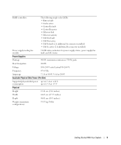
RAID controllers The following single-color LEDs: • Battery fault • Cache active • Controller fault • Controller power • Ethernet link • Ethernet activity • SAS Out fault • SAS Out active • SAS In fault (2 if additional In connector installed) • SAS In active (2 if additional In connector installed) Power supply/cooling fan module 3 LED status indicators for power supply status, power supply/fan fault, and AC status Power Supplies Wattage 488 W maximum continuous; 550 W peak Heat dissipation 200 W Voltage 100-240 V rated (...
RAID controllers The following single-color LEDs: • Battery fault • Cache active • Controller fault • Controller power • Ethernet link • Ethernet activity • SAS Out fault • SAS Out active • SAS In fault (2 if additional In connector installed) • SAS In active (2 if additional In connector installed) Power supply/cooling fan module 3 LED status indicators for power supply status, power supply/fan fault, and AC status Power Supplies Wattage 488 W maximum continuous; 550 W peak Heat dissipation 200 W Voltage 100-240 V rated (...
View
Page 12
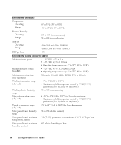
...40° to 149°F) Relative humidity Operating Storage 20% to 80% (noncondensing) 5% to 95% (noncondensing) Altitude Operating Storage -16 to 3048 m (-50 to 10,000 ft) -16 to 10,600 m (-50 to 35,000 ft) BTU per hour 1430 Environmental (Battery Backup Unit [BBU]) Maximum input power • +12 VDC +/-5% at 1 A...Operating temperature range: 5° to 55°C (41° to 131°F) Minimum retention time (life expectancy) 72 hours for 256-MB DDR-I DIMM, 2.5 V at 120 mA Working temperature range (dry bulb) • 5° to 55°C (41° to 131°F) • Maximum...
...40° to 149°F) Relative humidity Operating Storage 20% to 80% (noncondensing) 5% to 95% (noncondensing) Altitude Operating Storage -16 to 3048 m (-50 to 10,000 ft) -16 to 10,600 m (-50 to 35,000 ft) BTU per hour 1430 Environmental (Battery Backup Unit [BBU]) Maximum input power • +12 VDC +/-5% at 1 A...Operating temperature range: 5° to 55°C (41° to 131°F) Minimum retention time (life expectancy) 72 hours for 256-MB DDR-I DIMM, 2.5 V at 120 mA Working temperature range (dry bulb) • 5° to 55°C (41° to 131°F) • Maximum...


