Interoperability Guide
Page 2
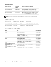
...system must be powered off. Hard Drives (External) Storage Enclosure RAID Controller Drive Type Drive Capacity PowerVault MD1000 PowerVault MD1200 PERC 6/E PERC H800 SATA 250GB, 500GB, 750GB, 1TB and 2TB Nearline SAS 500GB, 1TB and 2TB Network Interface Controllers (NIC) System NIC DL2000 DL2100 DL2200 (with ...later 11.6 or later 14.2.3 or later 12.0 or later 16.0 or later 12.5 or later 2 ׀ Dell PowerVault Backup to Disk Appliance Interoperability Guide Four (4) per PERC H800 with a single SAS cable. Eight (8) per PERC H800 with a single SAS cable...
...system must be powered off. Hard Drives (External) Storage Enclosure RAID Controller Drive Type Drive Capacity PowerVault MD1000 PowerVault MD1200 PERC 6/E PERC H800 SATA 250GB, 500GB, 750GB, 1TB and 2TB Nearline SAS 500GB, 1TB and 2TB Network Interface Controllers (NIC) System NIC DL2000 DL2100 DL2200 (with ...later 11.6 or later 14.2.3 or later 12.0 or later 16.0 or later 12.5 or later 2 ׀ Dell PowerVault Backup to Disk Appliance Interoperability Guide Four (4) per PERC H800 with a single SAS cable. Eight (8) per PERC H800 with a single SAS cable...
Interoperability Guide
Page 4
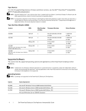
.... NOTE: If a tape library attached to the DL Backup to Disk Appliance Powered by Symantec contains more than those listed in the Dell PowerVault Compatibility Matrix. Operating System NOTE: Clustering is not supported on a protected server is not supported. System DL2000 DL2100 DL2200 Operating System Microsoft® Windows® Server 2008 Standard x64 Edition...
.... NOTE: If a tape library attached to the DL Backup to Disk Appliance Powered by Symantec contains more than those listed in the Dell PowerVault Compatibility Matrix. Operating System NOTE: Clustering is not supported on a protected server is not supported. System DL2000 DL2100 DL2200 Operating System Microsoft® Windows® Server 2008 Standard x64 Edition...

Getting Started Guide
Page 7
Connecting the Power Cable(s) Connect the system's power cable(s) to the bracket using the provided strap. Plug the other end of the power cable(s) into a loop as an uninterruptible power supply (UPS) or a power distribution unit (PDU). Getting Started With Your System 5 Securing the Power Cable(s) Bend the system power cable(s) into a grounded electrical outlet or a separate power source such as shown in the illustration and secure the cable(s) to the system.
Connecting the Power Cable(s) Connect the system's power cable(s) to the bracket using the provided strap. Plug the other end of the power cable(s) into a loop as an uninterruptible power supply (UPS) or a power distribution unit (PDU). Getting Started With Your System 5 Securing the Power Cable(s) Bend the system power cable(s) into a grounded electrical outlet or a separate power source such as shown in the illustration and secure the cable(s) to the system.

Getting Started Guide
Page 8
Turning on the System Press the power button on the system and the monitor. Installing the Optional Bezel Install the bezel (optional). 6 Getting Started With Your System The power indicator should light.
Turning on the System Press the power button on the system and the monitor. Installing the Optional Bezel Install the bezel (optional). 6 Getting Started With Your System The power indicator should light.

Getting Started Guide
Page 12
... USB 2.0-compliant One 4-pin, USB 2.0-compliant One internal flash memory card slot Video Video type Video memory Integrated Matrox G200 8 MB shared Power AC Power Supply (per power supply) Wattage 870 W (High Output) 570 W /200840 KB (Energy Smart) Voltage 90-264 VAC, autoranging, 47-63 Hz Heat ...) Maximum inrush current Under typical line conditions and over the entire system ambient operating range, the inrush current may reach 55 A per power supply for 10 ms or less. Batteries System battery CR 2032 3.0-V lithium coin cell RAID battery (optional) 3.7-V lithium ion battery pack...
... USB 2.0-compliant One 4-pin, USB 2.0-compliant One internal flash memory card slot Video Video type Video memory Integrated Matrox G200 8 MB shared Power AC Power Supply (per power supply) Wattage 870 W (High Output) 570 W /200840 KB (Energy Smart) Voltage 90-264 VAC, autoranging, 47-63 Hz Heat ...) Maximum inrush current Under typical line conditions and over the entire system ambient operating range, the inrush current may reach 55 A per power supply for 10 ms or less. Batteries System battery CR 2032 3.0-V lithium coin cell RAID battery (optional) 3.7-V lithium ion battery pack...

Getting Started Guide
Page 13
...99 in) with rack latches 44.31 cm (17.4 in) without rack latches 72.06 cm(28.4 in) with power supplies and bezel 68.07 cm(26.8) without power supplies and bezel 26.1 kg (57.54 lb) 17.7 kg (39 lb) Environmental NOTE: For additional information about environmental... measurements for 10 minutes in operational orientations Storage 1.54 Gms from 10-250 Hz for specific system configurations, see www.dell.com/environmental_datasheets Temperature ...
...99 in) with rack latches 44.31 cm (17.4 in) without rack latches 72.06 cm(28.4 in) with power supplies and bezel 68.07 cm(26.8) without power supplies and bezel 26.1 kg (57.54 lb) 17.7 kg (39 lb) Environmental NOTE: For additional information about environmental... measurements for 10 minutes in operational orientations Storage 1.54 Gms from 10-250 Hz for specific system configurations, see www.dell.com/environmental_datasheets Temperature ...

Hardware Owner's Manual
Page 3
Contents 1 About Your System 11 Accessing System Features During Startup 11 Front Panel Features and Indicators 12 LCD Panel Features 14 Home Screen 15 Setup Menu 16 View Menu 16 Hard-Drive Indicator Patterns for RAID 17 Back Panel Features and Indicators 18 Power Indicator Codes 20 NIC Indicator Codes 21 LCD Status Messages 22 Viewing Status Messages 22 Removing LCD Status Messages 22 System Messages 36 Warning Messages 52 Diagnostics Messages 52 Alert Messages 52 Other Information You May Need 53 Contents 3
Contents 1 About Your System 11 Accessing System Features During Startup 11 Front Panel Features and Indicators 12 LCD Panel Features 14 Home Screen 15 Setup Menu 16 View Menu 16 Hard-Drive Indicator Patterns for RAID 17 Back Panel Features and Indicators 18 Power Indicator Codes 20 NIC Indicator Codes 21 LCD Status Messages 22 Viewing Status Messages 22 Removing LCD Status Messages 22 System Messages 36 Warning Messages 52 Diagnostics Messages 52 Alert Messages 52 Other Information You May Need 53 Contents 3

Hardware Owner's Manual
Page 4
... Settings Screen 60 Boot Settings Screen 61 Integrated Devices Screen 62 PCI IRQ Assignments Screen 63 Serial Communication Screen 63 Embedded Server Management Screen 64 Power Management Screen 65 System Security Screen 66 Exit Screen 67 Entering the UEFI Boot Manager 68 Using the UEFI Boot Manager Navigation Keys 68 UEFI...
... Settings Screen 60 Boot Settings Screen 61 Integrated Devices Screen 62 PCI IRQ Assignments Screen 63 Serial Communication Screen 63 Embedded Server Management Screen 64 Power Management Screen 65 System Security Screen 66 Exit Screen 67 Entering the UEFI Boot Manager 68 Using the UEFI Boot Manager Navigation Keys 68 UEFI...

Hardware Owner's Manual
Page 5
... Hard Drive 82 Installing a Hot-Swap Hard Drive 82 Removing a Hard Drive From a Hard-Drive Carrier 83 Installing a Hard Drive Into a Hard-Drive Carrier 83 Power Supplies 85 Removing a Power Supply 85 Replacing a Power Supply 86 Removing the Power Supply Blank 87 Contents 5
... Hard Drive 82 Installing a Hot-Swap Hard Drive 82 Removing a Hard Drive From a Hard-Drive Carrier 83 Installing a Hard Drive Into a Hard-Drive Carrier 83 Power Supplies 85 Removing a Power Supply 85 Replacing a Power Supply 86 Removing the Power Supply Blank 87 Contents 5

Hardware Owner's Manual
Page 6
Installing the Power Supply Blank 87 Internal SD Module 87 Installing the Internal SD Module 87 Removing the Internal SD Module 89 Internal SD Flash Card 89 Installing ...
Installing the Power Supply Blank 87 Internal SD Module 87 Installing the Internal SD Module 87 Removing the Internal SD Module 89 Internal SD Flash Card 89 Installing ...
Hardware Owner's Manual
Page 9
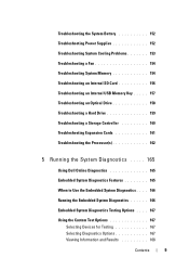
Troubleshooting the System Battery 152 Troubleshooting Power Supplies 152 Troubleshooting System Cooling Problems 153 Troubleshooting a Fan 154 Troubleshooting System Memory 154 Troubleshooting an Internal SD Card ...Hard Drive 159 Troubleshooting a Storage Controller 160 Troubleshooting Expansion Cards 161 Troubleshooting the Processor(s 162 5 Running the System Diagnostics . . . . . 165 Using Dell Online Diagnostics 165 Embedded System Diagnostics Features 165 When to Use the Embedded System Diagnostics . . . . 166 Running the Embedded System Diagnostics 166 Embedded System ...
Troubleshooting the System Battery 152 Troubleshooting Power Supplies 152 Troubleshooting System Cooling Problems 153 Troubleshooting a Fan 154 Troubleshooting System Memory 154 Troubleshooting an Internal SD Card ...Hard Drive 159 Troubleshooting a Storage Controller 160 Troubleshooting Expansion Cards 161 Troubleshooting the Processor(s 162 5 Running the System Diagnostics . . . . . 165 Using Dell Online Diagnostics 165 Embedded System Diagnostics Features 165 When to Use the Embedded System Diagnostics . . . . 166 Running the Embedded System Diagnostics 166 Embedded System ...

Hardware Owner's Manual
Page 13
...do so by qualified support personnel or by the operating system's documentation. About Your System 13 When the system bezel is installed, the power button is not accessible. Use this button only if directed to the system. NOTE: On ACPI-compliant operating systems, turning off . ...the control panel LCD menu. Item Indicator, Button, or Icon Connector 2 Power-on indicator, power button 3 NMI button 4 USB connectors (2) 5 Video connector 6 LCD menu buttons Description The power-on indicator lights when the system power is on the system, the video monitor can be pressed using the ...
...do so by qualified support personnel or by the operating system's documentation. About Your System 13 When the system bezel is installed, the power button is not accessible. Use this button only if directed to the system. NOTE: On ACPI-compliant operating systems, turning off . ...the control panel LCD menu. Item Indicator, Button, or Icon Connector 2 Power-on indicator, power button 3 NMI button 4 USB connectors (2) 5 Video connector 6 LCD menu buttons Description The power-on indicator lights when the system power is on the system, the video monitor can be pressed using the ...

Hardware Owner's Manual
Page 14
.... NOTE: If the system is operating correctly or when the system needs attention. Up to AC power and an error has been detected, the LCD lights amber regardless of whether the system has been powered on the back flash blue until one of the buttons is turned off through the iDRAC utility...
.... NOTE: If the system is operating correctly or when the system needs attention. Up to AC power and an error has been detected, the LCD lights amber regardless of whether the system has been powered on the back flash blue until one of the buttons is turned off through the iDRAC utility...

Hardware Owner's Manual
Page 17
Displays the temperature of the system in BTU/hr or Watts. Hard-Drive Indicators 1 2 1 drive-activity indicator (green) 2 drive-status indicator About Your System 17 Option Power Temperature Description Displays the power output of the system in Celsius or Fahrenheit. The display format can be configured in the "Set home" submenu of the Setup menu (see "Setup Menu"). Hard-Drive Indicator Patterns for RAID Figure 1-3. The display format can be configured in the "Set home" submenu of the Setup menu (see "Setup Menu").
Displays the temperature of the system in BTU/hr or Watts. Hard-Drive Indicators 1 2 1 drive-activity indicator (green) 2 drive-status indicator About Your System 17 Option Power Temperature Description Displays the power output of the system in Celsius or Fahrenheit. The display format can be configured in the "Set home" submenu of the Setup menu (see "Setup Menu"). Hard-Drive Indicator Patterns for RAID Figure 1-3. The display format can be configured in the "Set home" submenu of the Setup menu (see "Setup Menu").

Hardware Owner's Manual
Page 18
...: The drive status indicator remains off until all hard drives are not ready for insertion or removal during this time. Drives are initialized after system power is applied. Drive predicted failure Drive failed Drive rebuilding Drive online Back Panel Features and Indicators Figure 1-4.
...: The drive status indicator remains off until all hard drives are not ready for insertion or removal during this time. Drives are initialized after system power is applied. Drive predicted failure Drive failed Drive rebuilding Drive online Back Panel Features and Indicators Figure 1-4.

Hardware Owner's Manual
Page 19
...Your System 19 Item Indicator, Button, or Icon Connector 1 PCIe slot 1 2 PCIe slot 2 3 PCIe slot 3 4 PCIe slot 4 5 power supply 1 (PS1) 6 power supply 2 (PS2) 7 system identification button 8 system status indicator 9 system status indicator connector 10 Ethernet connectors (4) 11 USB connectors (2) Description PCI... arm Integrated 10/100/1000 NIC connectors Connects USB devices to locate a particular system within a rack. Provides a power on the back flash blue until one of the system Connector for attaching a system indicator extension cable that is pushed...
...Your System 19 Item Indicator, Button, or Icon Connector 1 PCIe slot 1 2 PCIe slot 2 3 PCIe slot 3 4 PCIe slot 4 5 power supply 1 (PS1) 6 power supply 2 (PS2) 7 system identification button 8 system status indicator 9 system status indicator connector 10 Ethernet connectors (4) 11 USB connectors (2) Description PCI... arm Integrated 10/100/1000 NIC connectors Connects USB devices to locate a particular system within a rack. Provides a power on the back flash blue until one of the system Connector for attaching a system indicator extension cable that is pushed...

Hardware Owner's Manual
Page 20
... an error condition and unexpected system shutdown. CAUTION: When correcting a power supply mismatch, replace only the power supply with the power supply. • Alternating green and amber - AC power is operational. Replace the power supply that has the flashing indicator with the other installed power supply. Item Indicator, Button, or Icon Connector 12 video connector Description...
... an error condition and unexpected system shutdown. CAUTION: When correcting a power supply mismatch, replace only the power supply with the power supply. • Alternating green and amber - AC power is operational. Replace the power supply that has the flashing indicator with the other installed power supply. Item Indicator, Button, or Icon Connector 12 video connector Description...

Hardware Owner's Manual
Page 21
Figure 1-5. off About Your System 21 NIC Indicators 1 2 1 link indicator 2 activity indicator Indicator Description Link and activity indicators are The NIC is not connected to the network. Power Supply Status Indicator 1 1 power supply status NIC Indicator Codes Figure 1-6.
Figure 1-5. off About Your System 21 NIC Indicators 1 2 1 link indicator 2 activity indicator Indicator Description Link and activity indicators are The NIC is not connected to the network. Power Supply Status Indicator 1 1 power supply status NIC Indicator Codes Figure 1-6.

Hardware Owner's Manual
Page 22
Network data is being sent or received. NOTE: If your system fails to boot, press the System ID button for the system. • Power cycle - LCD Status Messages The LCD messages consist of errors or status messages. For information on the LCD. Use the left and right arrow... buttons to highlight an error number, and press Select to events recorded in the Simple format. wait approximately ten seconds, reconnect the power cable, and restart the system. You can perform this task remotely, but you must take action to a normal state. Viewing Status Messages If a ...
Network data is being sent or received. NOTE: If your system fails to boot, press the System ID button for the system. • Power cycle - LCD Status Messages The LCD messages consist of errors or status messages. For information on the LCD. Use the left and right arrow... buttons to highlight an error number, and press Select to events recorded in the Simple format. wait approximately ten seconds, reconnect the power cable, and restart the system. You can perform this task remotely, but you must take action to a normal state. Viewing Status Messages If a ...

Hardware Owner's Manual
Page 23
... Motherboard battery failure. E1211 RAID Controller battery failure. Reseat PCIe cards. Cause Corrective Actions Check the system event log Remove AC power to thermal issues. Problems." See "Troubleshooting System Cooling Problems." RAID battery is outside of the System Battery." Table 1-1. E1116 ...persists, see "Troubleshooting Expansion Cards." allowable range. About Your System 23 LCD Status Messages Code Text E1000 Failsafe voltage error. Power cycle AC. CMOS battery is missing or See "Troubleshooting the the voltage is either missing, bad, or unable to recharge due...
... Motherboard battery failure. E1211 RAID Controller battery failure. Reseat PCIe cards. Cause Corrective Actions Check the system event log Remove AC power to thermal issues. Problems." See "Troubleshooting System Cooling Problems." RAID battery is outside of the System Battery." Table 1-1. E1116 ...persists, see "Troubleshooting Expansion Cards." allowable range. About Your System 23 LCD Status Messages Code Text E1000 Failsafe voltage error. Power cycle AC. CMOS battery is missing or See "Troubleshooting the the voltage is either missing, bad, or unable to recharge due...


